Part Details for ADF5901ACPZ-RL7 by Analog Devices Inc
Results Overview of ADF5901ACPZ-RL7 by Analog Devices Inc
- Distributor Offerings: (4 listings)
- Number of FFF Equivalents: (0 replacements)
- Tariff Estimator: (Available) NEW
- Number of Functional Equivalents: (0 options)
- CAD Models: (Available)
- Part Data Attributes: (Available)
- Reference Designs: (Not Available)
Tip: Data for a part may vary between manufacturers. You can filter for manufacturers on the top of the page next to the part image and part number.
Applications
Automotive
ADF5901ACPZ-RL7 Information
ADF5901ACPZ-RL7 by Analog Devices Inc is an Other Telecom IC.
Other Telecom ICs are under the broader part category of Telecommunication Circuits.
A telecommunications circuit transmits and receives information between points. Key components include transmitters, receivers, amplifiers, and multiplexers. Read more about Telecommunication Circuits on our Telecommunication Circuits part category page.
Price & Stock for ADF5901ACPZ-RL7
| Part # | Distributor | Description | Stock | Price | Buy | |
|---|---|---|---|---|---|---|
|
DISTI #
505-ADF5901ACPZ-RL7CT-ND
|
DigiKey | 24GHZ TX MMIC: VCO_PGA+ DUAL PA Min Qty: 1 Lead time: 10 Weeks Container: Digi-Reel®, Cut Tape (CT), Tape & Reel (TR) |
1365 In Stock |
|
$37.8340 / $55.8800 | Buy Now |
|
DISTI #
584-ADF5901ACPZ-RL7
|
Mouser Electronics | RF Transmitter 24 GHz VCO and PGA with 2-Channel PA Output RoHS: Compliant | 0 |
|
$37.7600 | Order Now |
|
|
Analog Devices Inc | 24GHz Tx MMIC: VCO_PGA+ dual P Min Qty: 1 Package Multiple: 1500 | 1773 |
|
$21.1800 / $49.1900 | Buy Now |
|
DISTI #
ADF5901ACPZ-RL7
|
Richardson RFPD | LINEAR ICS, OTHER RoHS: Compliant Min Qty: 1500 | 0 |
|
$37.7100 | Buy Now |
US Tariff Estimator: ADF5901ACPZ-RL7 by Analog Devices Inc
Calculations from this tool are estimations only for imports into the United States. Please refer to the distributor or manufacturer and reference official US government sources and authorities to verify any final purchase costs.
Part Details for ADF5901ACPZ-RL7
ADF5901ACPZ-RL7 CAD Models
-
Part Symbol
-
Footprint
-
3D Model
Available Download Formats
By downloading CAD models, you agree to our Terms & Conditions and Privacy Policy
ADF5901ACPZ-RL7 Part Data Attributes
|
|
ADF5901ACPZ-RL7
Analog Devices Inc
Buy Now
Datasheet
|
Compare Parts:
ADF5901ACPZ-RL7
Analog Devices Inc
Telecom Circuit, 1-Func
|
| Pbfree Code | No | |
| Rohs Code | Yes | |
| Part Life Cycle Code | Active | |
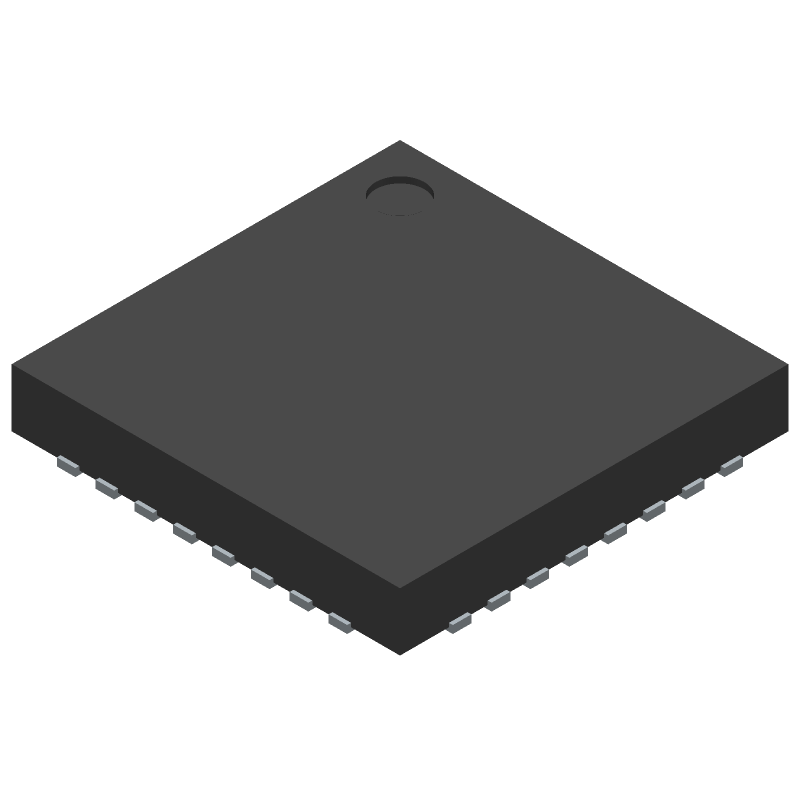
| Package Description | Lfcsp-32 | |
| Pin Count | 32 | |
| Manufacturer Package Code | CP-32-12 | |
| Reach Compliance Code | Compliant | |
| ECCN Code | EAR99 | |
| HTS Code | 8542.39.00.01 | |
| Date Of Intro | 2017-09-25 | |
| JESD-30 Code | S-XQCC-N32 | |
| Length | 5 Mm | |
| Moisture Sensitivity Level | 3 | |
| Number of Functions | 1 | |
| Number of Terminals | 32 | |
| Operating Temperature-Max | 105 °C | |
| Operating Temperature-Min | -40 °C | |
| Package Body Material | Unspecified | |
| Package Code | HVQCCN | |
| Package Equivalence Code | LCC32,.2SQ,20 | |
| Package Shape | Square | |
| Package Style | Chip Carrier, Heat Sink/Slug, Very Thin Profile | |
| Peak Reflow Temperature (Cel) | 260 | |
| Seated Height-Max | 0.8 Mm | |
| Supply Voltage-Nom | 3.3 V | |
| Surface Mount | Yes | |
| Telecom IC Type | Telecom Circuit | |
| Temperature Grade | Industrial | |
| Terminal Form | No Lead | |
| Terminal Pitch | 0.5 Mm | |
| Terminal Position | Quad | |
| Time@Peak Reflow Temperature-Max (s) | 30 | |
| Width | 5 Mm |
ADF5901ACPZ-RL7 Frequently Asked Questions (FAQ)
-
A good PCB layout for the ADF5901 involves keeping the input and output traces short and separate, using a solid ground plane, and placing decoupling capacitors close to the device. A 4-layer PCB with a dedicated ground plane is recommended. Additionally, it's essential to follow the layout guidelines provided in the datasheet and application notes.
-
Calibration of the ADF5901 involves setting the gain and offset registers to optimize performance for your specific application. This can be done using the provided evaluation software and following the calibration procedure outlined in the datasheet. It's essential to calibrate the device in the same environment and with the same signal chain as the final application.
-
The ADF5901 can operate up to 24 GHz, but the maximum frequency of operation depends on the specific application and the quality of the PCB layout. In general, the device can operate up to 18 GHz with a good PCB layout and proper decoupling. However, it's recommended to consult the datasheet and application notes for specific frequency limitations.
-
The ADF5901 can output up to 20 dBm, which can be damaging to other components if not handled properly. It's essential to use proper output matching and attenuation to prevent damage. Additionally, it's recommended to use a limiter or attenuator to prevent overvoltage conditions.
-
The ADF5901 requires a single 5 V power supply, and the recommended current is 350 mA. However, the actual current consumption may vary depending on the specific application and operating conditions. It's essential to ensure a stable power supply with adequate decoupling to prevent noise and instability.