
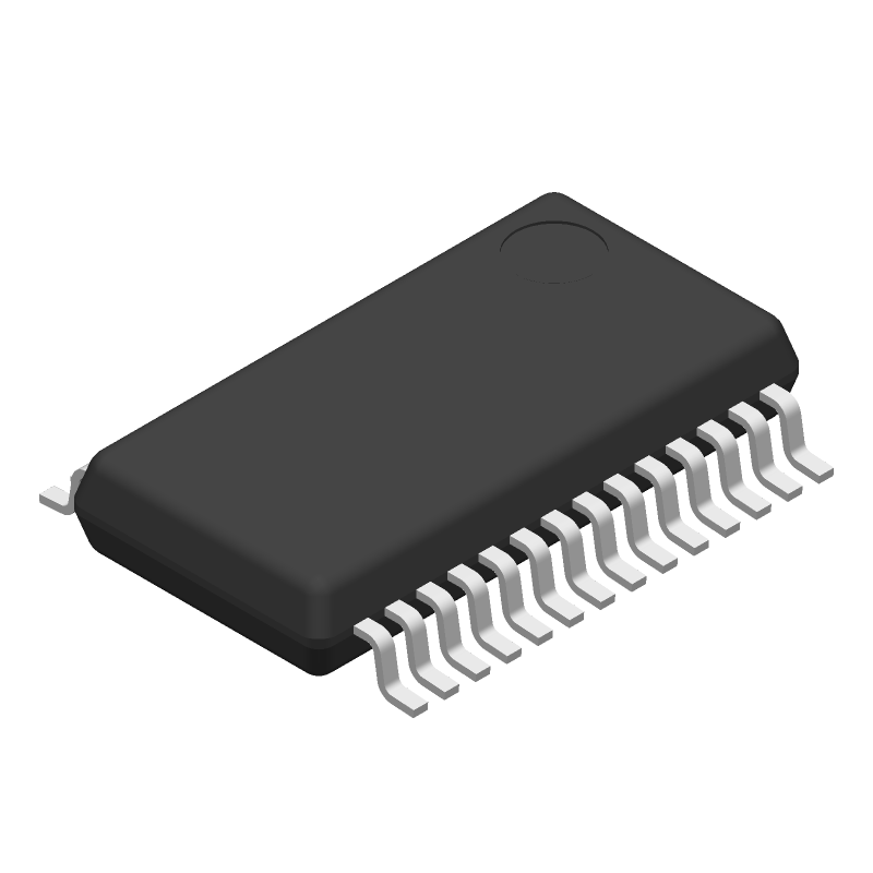
| Part Number | Manufacturer | Composite Price | Description | Compare |
|---|---|---|---|---|
| CDC536DB | Texas Instruments | $5.7982 | PLL Based Clock Driver, 536 Series, 6 True Output(s), 0 Inverted Output(s), BICMOS, PDSO28 | CDC536DBR vs CDC536DB |
| CDC536DBRG4 | Texas Instruments | Check for Price | PLL Based Clock Driver, 536 Series, 6 True Output(s), 0 Inverted Output(s), BICMOS, PDSO28 | CDC536DBR vs CDC536DBRG4 |
Part Details for CDC536DBR by Texas Instruments
Results Overview of CDC536DBR by Texas Instruments
- Distributor Offerings: (10 listings)
- Number of FFF Equivalents: (2 replacements)
- Tariff Estimator: (Available) NEW
- Number of Functional Equivalents: (3 options)
- CAD Models: (Available)
- Part Data Attributes: (Available)
- Reference Designs: (Not Available)
Tip: Data for a part may vary between manufacturers. You can filter for manufacturers on the top of the page next to the part image and part number.
CDC536DBR Information
CDC536DBR by Texas Instruments is a Clock Driver.
Clock Drivers are under the broader part category of Logic Components.
Digital logic governs the behavior of signals in electronic circuits, enabling complex decisions based on simple binary inputs (yes/no). Logic components perform operations from these signals. Read more about Logic Components on our Logic part category page.
Price & Stock for CDC536DBR
| Part # | Distributor | Description | Stock | Price | Buy | |
|---|---|---|---|---|---|---|
|
DISTI #
296-6707-2-ND
|
DigiKey | IC PLL CLOCK DRIVER 28SSOP Min Qty: 2000 Container: Tape & Reel |
0 Tape & Reel |
|
$7.8386 | Buy Now |
|
DISTI #
595-CDC536DBR
|
Mouser Electronics | Clock Drivers & Distribution 3.3V PLL Clock Drvr A 595-CDC536DB A 595 A 595-CDC536DB RoHS: Compliant | 0 |
|
$7.2600 | Order Now |
|
DISTI #
85975277
|
Verical | Clock Generator 25MHz to 100MHz-IN 100MHz-OUT 28-Pin SSOP T/R RoHS: Compliant Min Qty: 54 Package Multiple: 1 Date Code: 1001 | Americas - 8000 |
|
$5.5750 / $6.9750 | Buy Now |
|
DISTI #
85970649
|
Verical | Clock Generator 25MHz to 100MHz-IN 100MHz-OUT 28-Pin SSOP T/R RoHS: Compliant Min Qty: 54 Package Multiple: 1 Date Code: 0501 | Americas - 1443 |
|
$5.5750 / $6.9750 | Buy Now |
|
|
Bristol Electronics | Clock Generator 25MHz to 100MHz-IN 100MHz-OUT 28-Pin SSOP T/R Min Qty: 1 | 1974 |
|
$4.3922 / $10.2144 | Buy Now |
|
|
Quest Components | IC,SIX DISTRIBUTED-OUTPUT CLOCK DRIVER,BICMOS,SSOP,28PIN,PLASTIC | 9073 |
|
$1.4280 / $4.0800 | Buy Now |
|
|
Quest Components | IC,SIX DISTRIBUTED-OUTPUT CLOCK DRIVER,BICMOS,SSOP,28PIN,PLASTIC | 1579 |
|
$2.0400 / $4.0800 | Buy Now |
|
|
Quest Components | IC,SIX DISTRIBUTED-OUTPUT CLOCK DRIVER,BICMOS,SSOP,28PIN,PLASTIC | 1579 |
|
$4.7040 / $13.4400 | Buy Now |
|
|
Rochester Electronics | PLL Based Clock Driver, 536 Series, 6 True Output(s), 0 Inverted Output(s), BICMOS, PDSO28 RoHS: Compliant Status: Active Min Qty: 1 | 9443 |
|
$4.4600 / $5.5800 | Buy Now |
|
|
ComSIT USA | 3.3-V PHASE-LOCK LOOP CLOCK DRIVER WITH 3-STATE OUTPUT PLL Based Clock Driver, 536 Series, 6 True Output(s), 0 Inverted Output(s), BICMOS, PDSO28 ECCN: EAR99 RoHS: Not Compliant |
|
|
RFQ |
US Tariff Estimator: CDC536DBR by Texas Instruments
Calculations from this tool are estimations only for imports into the United States. Please refer to the distributor or manufacturer and reference official US government sources and authorities to verify any final purchase costs.
CDC536DBR CAD Models
-
Part Symbol
-
Footprint
-
3D Model
Available Download Formats
By downloading CAD models, you agree to our Terms & Conditions and Privacy Policy
CDC536DBR Part Data Attributes
|
|
CDC536DBR
Texas Instruments
Buy Now
Datasheet
|
Compare Parts:
CDC536DBR
Texas Instruments
PLL Based Clock Driver, 536 Series, 6 True Output(s), 0 Inverted Output(s), BICMOS, PDSO28
|
| Pbfree Code | Yes | |
| Rohs Code | Yes | |
| Part Life Cycle Code | Active | |
| Part Package Code | SSOP | |
| Package Description | Ssop-28 | |
| Pin Count | 28 | |
| ECCN Code | EAR99 | |
| HTS Code | 8542.39.00.90 | |
| Family | 536 | |
| Input Conditioning | Standard | |
| JESD-30 Code | R-PDSO-G28 | |
| JESD-609 Code | e4 | |
| Length | 10.2 Mm | |
| Load Capacitance (CL) | 30 Pf | |
| Logic IC Type | Pll Based Clock Driver | |
| Max I(ol) | 0.032 A | |
| Moisture Sensitivity Level | 1 | |
| Number of Functions | 1 | |
| Number of Inverted Outputs | ||
| Number of Terminals | 28 | |
| Number of True Outputs | 6 | |
| Operating Temperature-Max | 70 °C | |
| Operating Temperature-Min | ||
| Output Characteristics | 3-State | |
| Package Body Material | Plastic/Epoxy | |
| Package Code | SSOP | |
| Package Equivalence Code | SSOP28,.3 | |
| Package Shape | Rectangular | |
| Package Style | Small Outline, Shrink Pitch | |
| Packing Method | Tr | |
| Peak Reflow Temperature (Cel) | 260 | |
| Qualification Status | Not Qualified | |
| Same Edge Skew-Max (tskwd) | 0.5 Ns | |
| Seated Height-Max | 2 Mm | |
| Supply Voltage-Max (Vsup) | 3.6 V | |
| Supply Voltage-Min (Vsup) | 3 V | |
| Supply Voltage-Nom (Vsup) | 3.3 V | |
| Surface Mount | Yes | |
| Technology | Bicmos | |
| Temperature Grade | Commercial | |
| Terminal Finish | Nickel/Palladium/Gold (Ni/Pd/Au) | |
| Terminal Form | Gull Wing | |
| Terminal Pitch | 0.65 Mm | |
| Terminal Position | Dual | |
| Time@Peak Reflow Temperature-Max (s) | 30 | |
| Width | 5.3 Mm | |
| fmax-Min | 100 Mhz |
Alternate Parts for CDC536DBR
This table gives cross-reference parts and alternative options found for CDC536DBR. The Form Fit Function (FFF) tab will give you the options that are more likely to serve as direct pin-to-pin alternates or drop-in parts. The Functional Equivalents tab will give you options that are likely to match the same function of CDC536DBR, but it may not fit your design. Always verify details of parts you are evaluating, as these parts are offered as suggestions for what you are looking for and are not guaranteed.
CDC536DBR Frequently Asked Questions (FAQ)
-
The recommended power-up sequence is to apply VCC first, followed by VDD, and then the clock signal. This ensures proper initialization and prevents damage to the device.
-
To optimize for low power consumption, use the lowest possible clock frequency, disable unused features, and use the power-down mode when not in use. Additionally, consider using a lower voltage supply and optimizing the output load capacitance.
-
The maximum clock frequency is 100 MHz, but it's recommended to use a frequency below 80 MHz to ensure reliable operation and minimize jitter.
-
To handle clock domain crossing, use a synchronizer circuit or a FIFO buffer to transfer data between clock domains. The CDC536DBR provides a built-in synchronizer for this purpose.
-
Use a symmetrical layout, keep the clock signal away from noisy signals, and use a low-impedance path for the clock signal. Additionally, use a decoupling capacitor between VCC and GND to reduce noise and ensure reliable operation.