-
Part Symbol
-
Footprint
-
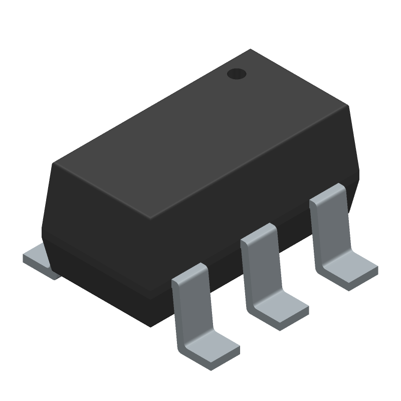
3D Model
Available Download Formats
By downloading CAD models, you agree to our Terms & Conditions and Privacy Policy
Directional Coupler, 2300MHz Min, 2600MHz Max, 0.7dB Insertion Loss-Max
Tip: Data for a part may vary between manufacturers. You can filter for manufacturers on the top of the page next to the part image and part number.
D17IA+ by Mini-Circuits is an RF/Microwave Coupler.
RF/Microwave Couplers are under the broader part category of RF and Microwave Components.
RF and Microwave Engineering focuses on the design and operation of devices that transmit or receive radio waves. The main distinction between RF and microwave engineering is their wavelength, which influences how energy is transmitted and used in various applications. Read more about RF and Microwave Components on our RF and Microwave part category page.
| Part # | Distributor | Description | Stock | Price | Buy | |
|---|---|---|---|---|---|---|
|
DISTI #
3157-D17IA+CT-ND
|
DigiKey | DIR COUP, 2300 - 2600 MHZ, 50 Min Qty: 1 Lead time: 12 Weeks Container: Digi-Reel®, Cut Tape (CT), Tape & Reel (TR) |
868 In Stock |
|
$1.2625 / $7.5100 | Buy Now |
|
DISTI #
139-D17IA+
|
Mouser Electronics | Signal Conditioning 17.1 dB SMT Directional Coupler, 2300 - 2600 MHz, 50? RoHS: Compliant | 526 |
|
$1.3100 / $7.5100 | Buy Now |
By downloading CAD models, you agree to our Terms & Conditions and Privacy Policy
|
|
D17IA+
Mini-Circuits
Buy Now
Datasheet
|
Compare Parts:
D17IA+
Mini-Circuits
Directional Coupler, 2300MHz Min, 2600MHz Max, 0.7dB Insertion Loss-Max
|
| Rohs Code | Yes | |
| Part Life Cycle Code | Active | |
| Reach Compliance Code | Unknown | |
| ECCN Code | EAR99 | |
| Characteristic Impedance | 50 Ω | |
| Construction | Component | |
| Input Power-Max (CW) | 36.02 Dbm | |
| Insertion Loss-Max | 0.7 Db | |
| Mounting Feature | Surface Mount | |
| Number of Terminals | 6 | |
| Operating Frequency-Max | 2600 Mhz | |
| Operating Frequency-Min | 2300 Mhz | |
| Operating Temperature-Max | 105 °C | |
| Operating Temperature-Min | -40 °C | |
| Package Body Material | Plastic/Epoxy | |
| RF/Microwave Device Type | Directional Coupler | |
| Surface Mount | Yes | |
| VSWR-Max | 1.2 |
Mini-Circuits provides a recommended PCB layout and footprint for the D17IA+ in their application notes. It's essential to follow these guidelines to ensure optimal performance and minimize parasitic effects.
The D17IA+ has a 50 ohm input and output impedance. To impedance match, use a pi-network or a T-network topology with resistors and capacitors. Mini-Circuits also provides a matching calculator tool on their website.
The D17IA+ can handle up to 1W of input power. Exceeding this limit may cause damage to the device or affect its performance. It's essential to ensure that the input power is within the specified range.
To reduce the noise figure of the D17IA+, ensure that the input signal is strong, use a low-noise voltage regulator, and keep the device away from noise sources. Additionally, using a noise-reducing component, such as a ferrite bead, can help minimize noise.
While the D17IA+ is designed for 50 ohm systems, it can be used in non-50 ohm systems with proper impedance matching. However, this may affect the device's performance, and additional circuitry may be required to achieve optimal results.