
Part Details for INA121PA by Texas Instruments
Results Overview of INA121PA by Texas Instruments
- Distributor Offerings: (2 listings)
- Number of FFF Equivalents: (0 replacements)
- Tariff Estimator: (Available) NEW
- Number of Functional Equivalents: (0 options)
- CAD Models: (Available)
- Part Data Attributes: (Available)
- Reference Designs: (Not Available)
Tip: Data for a part may vary between manufacturers. You can filter for manufacturers on the top of the page next to the part image and part number.
INA121PA Information
INA121PA by Texas Instruments is an Instrumentation Amplifier.
Instrumentation Amplifiers are under the broader part category of Amplifier Circuits.
Amplifier circuits use external power to increase the amplitude of an input signal. They can be used to perform linear amplifications or logarithmic functions. Read more about Amplifier Circuits on our Amplifier Circuits part category page.
Price & Stock for INA121PA
| Part # | Distributor | Description | Stock | Price | Buy | |
|---|---|---|---|---|---|---|
|
DISTI #
595-INA121PA
|
Mouser Electronics | Instrumentation Amplifiers FET-Input Low Power Instrumentation Amp RoHS: Compliant | 763 |
|
$5.5400 / $9.2500 | Buy Now |
|
DISTI #
INA121PA
|
TME | IC: instrumentation amplifier, 600kHz, Ch: 1, ±2.25÷18VDC, DIP8 Min Qty: 1 | 201 |
|
$4.8000 / $8.4600 | Buy Now |
US Tariff Estimator: INA121PA by Texas Instruments
Calculations from this tool are estimations only for imports into the United States. Please refer to the distributor or manufacturer and reference official US government sources and authorities to verify any final purchase costs.
INA121PA CAD Models
-
Part Symbol
-
Footprint
-
3D Model
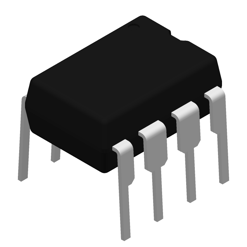
Available Download Formats
By downloading CAD models, you agree to our Terms & Conditions and Privacy Policy
INA121PA Part Data Attributes
|
|
INA121PA
Texas Instruments
Buy Now
Datasheet
|
Compare Parts:
INA121PA
Texas Instruments
Instrumentation Amplifier, 1 Func, 500uV Offset-Max, 0.6MHz Band Width, PDIP8
|
| Pbfree Code | Yes | |
| Rohs Code | Yes | |
| Part Life Cycle Code | Active | |
| Part Package Code | DIP | |
| Package Description | Pdip-8 | |
| Pin Count | 8 | |
| ECCN Code | EAR99 | |
| HTS Code | 8542.33.00.01 | |
| Amplifier Type | Instrumentation Amplifier | |
| Average Bias Current-Max (IIB) | 0.00005 µA | |
| Bandwidth (3dB)-Nom | 0.6 Mhz | |
| Bias Current-Max (IIB) @25C | 0.00005 µA | |
| Common-mode Reject Ratio-Min | 106 Db | |
| Input Offset Current-Max (IIO) | 5e-7 µA | |
| Input Offset Voltage-Max | 500 µV | |
| JESD-30 Code | R-PDIP-T8 | |
| JESD-609 Code | e4 | |
| Length | 9.81 Mm | |
| Neg Supply Voltage Limit-Max | -18 V | |
| Neg Supply Voltage-Nom (Vsup) | -15 V | |
| Non-linearity-Max | 0.002% | |
| Number of Functions | 1 | |
| Number of Terminals | 8 | |
| Operating Temperature-Max | 85 °C | |
| Operating Temperature-Min | -40 °C | |
| Package Body Material | Plastic/Epoxy | |
| Package Code | DIP | |
| Package Equivalence Code | DIP8,.3 | |
| Package Shape | Rectangular | |
| Package Style | In-Line | |
| Packing Method | Tube | |
| Qualification Status | Not Qualified | |
| Seated Height-Max | 5.08 Mm | |
| Slew Rate-Nom | 0.7 V/Us | |
| Supply Current-Max | 0.53 Ma | |
| Supply Voltage Limit-Max | 18 V | |
| Supply Voltage-Nom (Vsup) | 15 V | |
| Surface Mount | No | |
| Temperature Grade | Industrial | |
| Terminal Finish | Nickel/Palladium/Gold (Ni/Pd/Au) | |
| Terminal Form | Through-Hole | |
| Terminal Pitch | 2.54 Mm | |
| Terminal Position | Dual | |
| Voltage Gain-Max | 10000 | |
| Voltage Gain-Min | 1 | |
| Voltage Gain-Nom | 10 | |
| Width | 7.62 Mm |
INA121PA Frequently Asked Questions (FAQ)
-
The INA121PA can handle input voltages up to ±40V, but it's recommended to keep the input voltage within ±20V for optimal performance and to prevent damage to the device.
-
To ensure accurate gain settings, make sure to use a precise resistor value for the gain-setting resistor (Rg) and ensure that the resistor is of high precision (e.g., 1% or better). Additionally, consider using a resistor network or a digital potentiometer for more precise gain control.
-
To minimize noise and interference, place the INA121PA close to the signal source, use a ground plane, and keep the input traces as short as possible. Also, avoid running digital signals near the INA121PA's analog signals, and use shielding or guard rings to protect the sensitive analog signals.
-
To handle EMI and RFI interference, use a shielded enclosure, add ferrite beads or chokes to the input lines, and consider using a common-mode filter or a differential filter to reject common-mode noise. Additionally, ensure good grounding and decoupling practices.
-
Decouple the power supply lines with a 10uF ceramic capacitor and a 100nF ceramic capacitor in parallel, placed as close to the INA121PA's power pins as possible. This helps to filter out noise and ripple on the power supply lines.