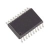
Part Details for L9639 by STMicroelectronics
Results Overview of L9639 by STMicroelectronics
- Distributor Offerings: (2 listings)
- Number of FFF Equivalents: (0 replacements)
- Tariff Estimator: (Available) NEW
- Number of Functional Equivalents: (0 options)
- CAD Models: (Request Part)
- Part Data Attributes: (Available)
- Reference Designs: (Not Available)
Tip: Data for a part may vary between manufacturers. You can filter for manufacturers on the top of the page next to the part image and part number.
L9639 Information
L9639 by STMicroelectronics is an Other Signal Circuit.
Other Signal Circuits are under the broader part category of Signal Circuits.
A signal is an electronic means of transmitting information, either as an analog signal with continuous values or a digital signal with discrete values. Signals are used in various systems and networks. Read more about Signal Circuits on our Signal Circuits part category page.
Price & Stock for L9639
| Part # | Distributor | Description | Stock | Price | Buy | |
|---|---|---|---|---|---|---|
|
DISTI #
L9639-ND
|
DigiKey | IC MOTOR DRIVER 8V-17V 20POWERSO Min Qty: 310 Container: Tube |
0 Tube |
|
$4.5662 | Buy Now |
|
|
Vyrian | Analog Circuit, 1 Func, BCDMOS, PDSO20 | 4475 |
|
RFQ |
US Tariff Estimator: L9639 by STMicroelectronics
Calculations from this tool are estimations only for imports into the United States. Please refer to the distributor or manufacturer and reference official US government sources and authorities to verify any final purchase costs.
L9639 Part Data Attributes
|
|
L9639
STMicroelectronics
Buy Now
Datasheet
|
Compare Parts:
L9639
STMicroelectronics
Analog Circuit, 1 Func, BCDMOS, PDSO20
|
| Rohs Code | Yes | |
| Part Life Cycle Code | Obsolete | |
| Part Package Code | SOIC | |
| Package Description | Mo-166, Sop-20 | |
| Pin Count | 20 | |
| HTS Code | 8542.39.00.01 | |
| Analog IC - Other Type | Analog Circuit | |
| JESD-30 Code | R-PDSO-G20 | |
| JESD-609 Code | e3 | |
| Length | 15.9 Mm | |
| Number of Functions | 1 | |
| Number of Terminals | 20 | |
| Operating Temperature-Max | 125 °C | |
| Operating Temperature-Min | -40 °C | |
| Package Body Material | Plastic/Epoxy | |
| Package Code | SOP | |
| Package Equivalence Code | SOP20,.56 | |
| Package Shape | Rectangular | |
| Package Style | Small Outline | |
| Qualification Status | Not Qualified | |
| Seated Height-Max | 3.6 Mm | |
| Supply Current-Max (Isup) | 0.2 Ma | |
| Supply Voltage-Max (Vsup) | 17 V | |
| Supply Voltage-Min (Vsup) | 8 V | |
| Supply Voltage-Nom (Vsup) | 12 V | |
| Surface Mount | Yes | |
| Technology | Bcdmos | |
| Temperature Grade | Automotive | |
| Terminal Finish | Matte Tin | |
| Terminal Form | Gull Wing | |
| Terminal Pitch | 1.27 Mm | |
| Terminal Position | Dual | |
| Width | 11 Mm |
L9639 Frequently Asked Questions (FAQ)
-
STMicroelectronics provides a recommended PCB layout in the application note AN4553, which includes guidelines for component placement, thermal management, and routing to ensure optimal performance and minimize electromagnetic interference (EMI).
-
The L9639 datasheet provides a list of recommended external components, including capacitors, resistors, and inductors. Additionally, STMicroelectronics offers a dedicated tool, the L9639 Component Selector, to help engineers select the optimal components for their specific application.
-
The L9639 is rated for operation from -40°C to 150°C (junction temperature), but the maximum operating temperature range depends on the specific application and the thermal management design. Engineers should consult the datasheet and application notes for guidance on thermal design and derating.
-
The L9639 has a built-in overcurrent protection feature, which can be enabled by connecting the OCP pin to a resistor and capacitor network. The application note AN4553 provides a detailed example of how to implement overcurrent protection and adjust the threshold and response time to suit specific application requirements.
-
The L9639 is designed for high-voltage applications up to 600V, but engineers should ensure that the device is properly configured and protected to handle the high voltage. This includes selecting suitable external components, designing a robust PCB layout, and implementing adequate thermal management.