| Part Number | Manufacturer | Composite Price | Description | Compare |
|---|---|---|---|---|
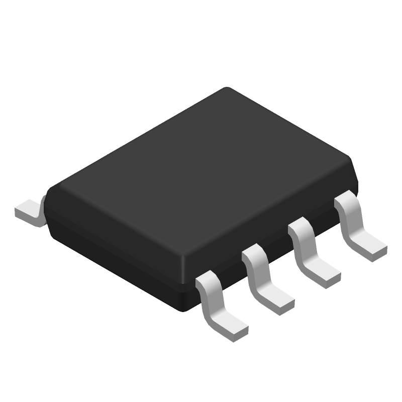
| OPA642UB | Rochester Electronics LLC | Check for Price | OP-AMP, 1000uV OFFSET-MAX, 210MHz BAND WIDTH, PDSO8, PLASTIC, SOIC-8 | OPA642UB vs OPA642UB |
Part Details for OPA642UB by Texas Instruments
Results Overview of OPA642UB by Texas Instruments
- Distributor Offerings: (1 listing)
- Number of FFF Equivalents: (1 replacement)
- Tariff Estimator: (Available) NEW
- Number of Functional Equivalents: (8 options)
- CAD Models: (Available)
- Part Data Attributes: (Available)
- Reference Designs: (Not Available)
Tip: Data for a part may vary between manufacturers. You can filter for manufacturers on the top of the page next to the part image and part number.
Applications
Education and Research
Environmental Monitoring
Industrial Automation
Agriculture Technology
Medical Imaging
OPA642UB Information
OPA642UB by Texas Instruments is an Operational Amplifier.
Operational Amplifiers are under the broader part category of Amplifier Circuits.
Amplifier circuits use external power to increase the amplitude of an input signal. They can be used to perform linear amplifications or logarithmic functions. Read more about Amplifier Circuits on our Amplifier Circuits part category page.
Price & Stock for OPA642UB
| Part # | Distributor | Description | Stock | Price | Buy | |
|---|---|---|---|---|---|---|
|
|
Vyrian | Operational Amplifier, 1 Func, 1000uV Offset-Max, BIPolar, PDSO8 | 4594 |
|
RFQ |
US Tariff Estimator: OPA642UB by Texas Instruments
Calculations from this tool are estimations only for imports into the United States. Please refer to the distributor or manufacturer and reference official US government sources and authorities to verify any final purchase costs.
OPA642UB CAD Models
-
Part Symbol
-
Footprint
-
3D Model
Available Download Formats
By downloading CAD models, you agree to our Terms & Conditions and Privacy Policy
OPA642UB Part Data Attributes
|
|
OPA642UB
Texas Instruments
Buy Now
Datasheet
|
Compare Parts:
OPA642UB
Texas Instruments
Operational Amplifier, 1 Func, 1000uV Offset-Max, BIPolar, PDSO8
|
| Pbfree Code | No | |
| Part Life Cycle Code | Obsolete | |
| Part Package Code | SOIC | |
| Package Description | Sop-8 | |
| Pin Count | 8 | |
| ECCN Code | EAR99 | |
| HTS Code | 8542.33.00.01 | |
| Amplifier Type | Operational Amplifier | |
| Architecture | Voltage-Feedback | |
| Average Bias Current-Max (IIB) | 70 µA | |
| Bias Current-Max (IIB) @25C | 45 µA | |
| Common-mode Reject Ratio-Min | 80 Db | |
| Common-mode Reject Ratio-Nom | 90 Db | |
| Frequency Compensation | Yes | |
| Input Offset Current-Max (IIO) | 3 µA | |
| Input Offset Voltage-Max | 1000 µV | |
| JESD-30 Code | R-PDSO-G5 | |
| Low-Bias | No | |
| Low-Offset | No | |
| Micropower | No | |
| Neg Supply Voltage Limit-Max | -6 V | |
| Neg Supply Voltage-Nom (Vsup) | -5 V | |
| Number of Functions | 1 | |
| Number of Terminals | 8 | |
| Operating Temperature-Max | 85 °C | |
| Operating Temperature-Min | -40 °C | |
| Package Body Material | Plastic/Epoxy | |
| Package Code | SOP | |
| Package Equivalence Code | SOP8(UNSPEC) | |
| Package Shape | Rectangular | |
| Package Style | Small Outline | |
| Peak Reflow Temperature (Cel) | Not Specified | |
| Power | No | |
| Programmable Power | No | |
| Qualification Status | Not Qualified | |
| Slew Rate-Nom | 380 V/Us | |
| Supply Current-Max | 26 Ma | |
| Supply Voltage Limit-Max | 6 V | |
| Supply Voltage-Nom (Vsup) | 5 V | |
| Surface Mount | Yes | |
| Technology | Bipolar | |
| Temperature Grade | Industrial | |
| Terminal Form | Gull Wing | |
| Terminal Position | Dual | |
| Time@Peak Reflow Temperature-Max (s) | Not Specified | |
| Unity Gain BW-Nom | 210000 | |
| Voltage Gain-Min | 17782.7941 | |
| Wideband | Yes |
Alternate Parts for OPA642UB
This table gives cross-reference parts and alternative options found for OPA642UB. The Form Fit Function (FFF) tab will give you the options that are more likely to serve as direct pin-to-pin alternates or drop-in parts. The Functional Equivalents tab will give you options that are likely to match the same function of OPA642UB, but it may not fit your design. Always verify details of parts you are evaluating, as these parts are offered as suggestions for what you are looking for and are not guaranteed.
OPA642UB Frequently Asked Questions (FAQ)
-
For optimal performance, it is recommended to follow good PCB design practices, such as keeping the input and output traces short and away from noise sources, using a solid ground plane, and decoupling the power supply pins with 0.1uF and 10uF capacitors. Additionally, the datasheet provides a recommended layout diagram that can be used as a starting point.
-
The OPA642UB has a high input bias current, which can cause voltage drops across the input resistors. To mitigate this, use a low-impedance source, such as a voltage divider or a buffer amplifier, to drive the input pins. Additionally, consider using a current-limiting resistor in series with the input pins to prevent excessive current draw.
-
The OPA642UB can drive capacitive loads up to 100pF without oscillation. However, it is recommended to use a series resistor (Rs) to dampen the capacitive load and prevent oscillation. The value of Rs can be calculated using the formula Rs = 10 / (2 * pi * f * C), where f is the frequency of operation and C is the capacitive load.
-
To ensure stability and prevent oscillation, follow the recommended compensation capacitor values and placement, use a low-ESR capacitor for power supply decoupling, and avoid using long input traces or cables. Additionally, consider adding a small series resistor (Rs) to the output pin to dampen the output stage.
-
The OPA642UB can operate from a single supply voltage of 4.5V to 12V, or from a dual supply voltage of ±2.25V to ±6V. However, it is recommended to operate the device within the specified voltage range to ensure optimal performance and prevent damage to the device.