-
Part Symbol
-
Footprint
-
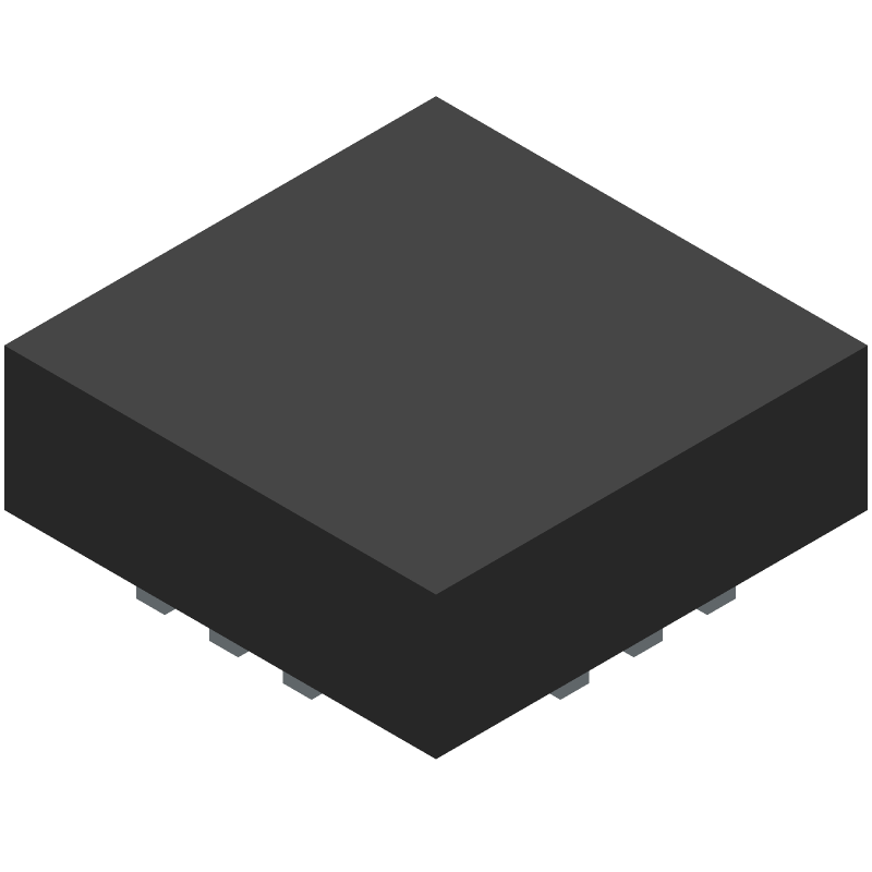
3D Model
Available Download Formats
By downloading CAD models, you agree to our Terms & Conditions and Privacy Policy
VARIABLE GAIN AMPLIFIER
Tip: Data for a part may vary between manufacturers. You can filter for manufacturers on the top of the page next to the part image and part number.
PVGA-123+ by Mini-Circuits is an RF/Microwave Amplifier.
RF/Microwave Amplifiers are under the broader part category of RF and Microwave Components.
RF and Microwave Engineering focuses on the design and operation of devices that transmit or receive radio waves. The main distinction between RF and microwave engineering is their wavelength, which influences how energy is transmitted and used in various applications. Read more about RF and Microwave Components on our RF and Microwave part category page.
| Part # | Distributor | Description | Stock | Price | Buy | |
|---|---|---|---|---|---|---|
|
DISTI #
3157-PVGA-123+CT-ND
|
DigiKey | SMT VGA, 0.4 - 12 GHZ, 50 Min Qty: 1 Lead time: 12 Weeks Container: Digi-Reel®, Cut Tape (CT), Tape & Reel (TR) |
596 In Stock |
|
$27.0501 / $45.5400 | Buy Now |
|
DISTI #
139-PVGA-123+
|
Mouser Electronics | Special Purpose Amplifiers SMT Variable Gain Amplifier, 0.4 - 12 GHz, 50 Ohm RoHS: Compliant | 66 |
|
$29.1600 / $45.5400 | Buy Now |
By downloading CAD models, you agree to our Terms & Conditions and Privacy Policy
Mini-Circuits recommends a 4-layer PCB with a solid ground plane, and a star-grounding scheme to minimize noise and ensure stability. A detailed application note is available on the Mini-Circuits website.
To achieve the specified gain flatness and bandwidth, ensure that the input and output are properly matched, and the device is operated within the recommended operating conditions. Additionally, use a low-loss PCB material and minimize the length of the input and output traces.
The maximum safe operating temperature for the PVGA-123+ is 85°C. Operating the device above this temperature may reduce its reliability and lifespan.
While the PVGA-123+ is optimized for 50 ohm systems, it can be used in non-50 ohm systems with some performance degradation. However, the input and output impedance must be matched to the system impedance to ensure optimal performance.
Mini-Circuits recommends a decoupling scheme that includes a 10uF capacitor in parallel with a 100nF capacitor, placed as close as possible to the device's power supply pins. This helps to reduce noise and ensure stable operation.