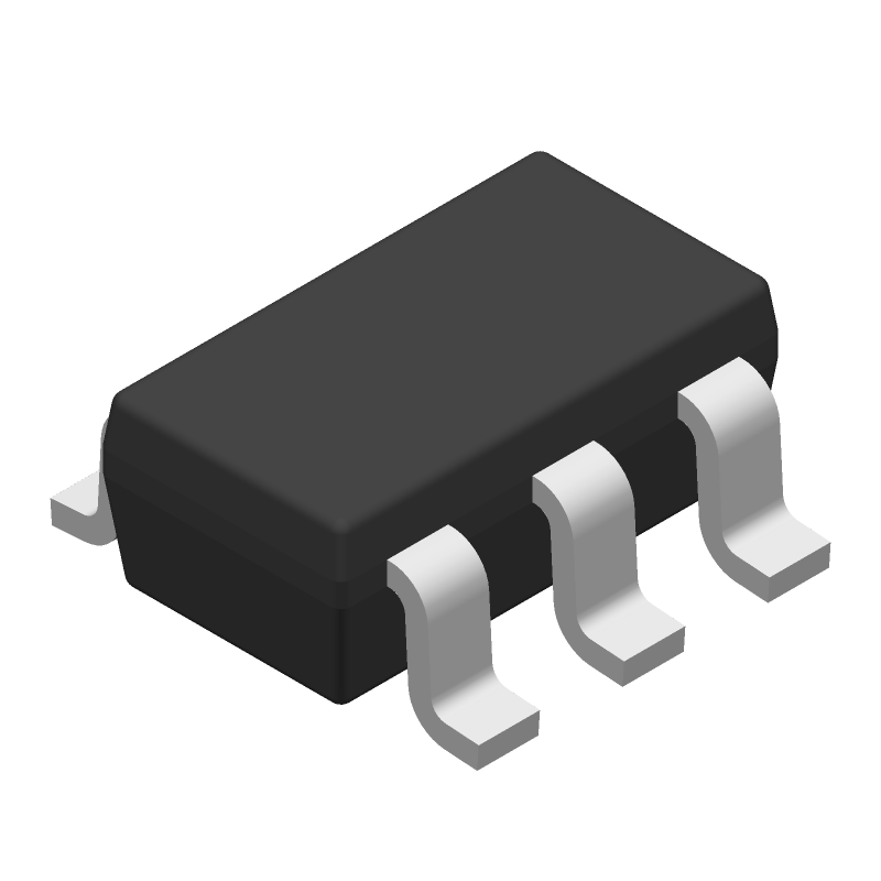
Tip: Data for a part may vary between manufacturers. You can filter for manufacturers on the top of the page next to the part image and part number.
ApplicationsIndustrial AutomationComputing and Data StorageMedical ImagingCommunication and Networking
SN74AXCH1T45DBVR Information
SN74AXCH1T45DBVR by Texas Instruments is a Bus Driver/Transceiver.
Bus Driver/Transceivers are under the broader part category of Logic Components.
Digital logic governs the behavior of signals in electronic circuits, enabling complex decisions based on simple binary inputs (yes/no). Logic components perform operations from these signals. Read more about Logic Components on our Logic part category page.
US Tariff Estimator: SN74AXCH1T45DBVR by Texas Instruments
Calculations from this tool are estimations only for imports into the United States. Please refer to the distributor or manufacturer and reference official US government sources and authorities to verify any final purchase costs.
This table gives cross-reference parts and alternative options found for SN74AXCH1T45DBVR. The Form Fit Function (FFF) tab will give you the options that are more likely to serve as direct pin-to-pin alternates or drop-in parts. The Functional Equivalents tab will give you options that are likely to match the same function of SN74AXCH1T45DBVR, but it may not fit your design. Always verify details of parts you are evaluating, as these parts are offered as suggestions for what you are looking for and are not guaranteed.
The maximum operating frequency of the SN74AXCH1T45DBVR is 500 MHz.
To ensure signal integrity, use a low-impedance PCB design, minimize trace lengths, and use termination resistors as needed. Also, follow the recommended layout guidelines in the datasheet.
Yes, the SN74AXCH1T45DBVR is compatible with 3.3V systems. However, ensure that the input voltage (VCC) is within the recommended operating range of 2.3V to 3.6V.
To ensure proper operation, power up the VCC pin before applying input signals. Also, ensure that the input signals are stable before powering up the device.
The recommended termination scheme is a series resistor (Rs) and a parallel capacitor (Cp) at the output. The values of Rs and Cp depend on the specific application and PCB design.