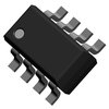
Part Details for SST441 by Calogic Inc
Results Overview of SST441 by Calogic Inc
- Distributor Offerings: (1 listing)
- Number of FFF Equivalents: (0 replacements)
- Tariff Estimator: (Available) NEW
- Number of Functional Equivalents: (0 options)
- CAD Models: (Request Part)
- Part Data Attributes: (Available)
- Reference Designs: (Not Available)
Tip: Data for a part may vary between manufacturers. You can filter for manufacturers on the top of the page next to the part image and part number.
SST441 Information
SST441 by Calogic Inc is an RF Small Signal Field-Effect Transistor.
RF Small Signal Field-Effect Transistors are under the broader part category of Transistors.
A transistor is a small semiconductor device used to amplify, control, or create electrical signals. When selecting a transistor, factors such as voltage, current rating, gain, and power dissipation must be considered, with common types. Read more about Transistors on our Transistors part category page.
Price & Stock for SST441
| Part # | Distributor | Description | Stock | Price | Buy | |
|---|---|---|---|---|---|---|
|
|
NAC | RF Small Signal Field-EffectTransistor,2-Element,Ultra High Frequency Band,Silicon,N-Channel,Junction FET RoHS: Not Compliant Min Qty: 500 Package Multiple: 97 Container: Tube | 0 |
|
$3.0000 / $3.3200 | Buy Now |
US Tariff Estimator: SST441 by Calogic Inc
Calculations from this tool are estimations only for imports into the United States. Please refer to the distributor or manufacturer and reference official US government sources and authorities to verify any final purchase costs.
SST441 Part Data Attributes
|
|
SST441
Calogic Inc
Buy Now
Datasheet
|
Compare Parts:
SST441
Calogic Inc
RF Small Signal Field-Effect Transistor, 2-Element, Ultra High Frequency Band, Silicon, N-Channel, Junction FET
|
| Pbfree Code | No | |
| Part Life Cycle Code | Active | |
| Part Package Code | SOT | |
| Package Description | Plastic, So-8 | |
| Pin Count | 8 | |
| ECCN Code | EAR99 | |
| HTS Code | 8542.90.00.00 | |
| Configuration | Separate, 2 Elements | |
| FET Technology | Junction | |
| Highest Frequency Band | Ultra High Frequency Band | |
| JESD-30 Code | R-PDSO-G8 | |
| Number of Elements | 2 | |
| Number of Terminals | 8 | |
| Operating Mode | Depletion Mode | |
| Operating Temperature-Max | 150 °C | |
| Package Body Material | Plastic/Epoxy | |
| Package Shape | Rectangular | |
| Package Style | Small Outline | |
| Peak Reflow Temperature (Cel) | Not Specified | |
| Polarity/Channel Type | N-Channel | |
| Power Dissipation-Max (Abs) | 0.5 W | |
| Qualification Status | Not Qualified | |
| Surface Mount | Yes | |
| Terminal Form | Gull Wing | |
| Terminal Position | Dual | |
| Time@Peak Reflow Temperature-Max (s) | Not Specified | |
| Transistor Application | Amplifier | |
| Transistor Element Material | Silicon |
SST441 Frequently Asked Questions (FAQ)
-
The recommended operating temperature range for the SST441 is -40°C to +85°C, with a storage temperature range of -55°C to +125°C.
-
To ensure proper biasing, the SST441 requires a single 3.3V or 5V power supply, and the input voltage (VIN) should be within the recommended range of 2.7V to 5.5V. Additionally, the output voltage (VOUT) should be decoupled with a 10uF capacitor to minimize noise and ensure stability.
-
The SST441 is capable of delivering up to 1A of output current, making it suitable for a wide range of applications, including powering microcontrollers, sensors, and other low-power devices.
-
The SST441 has a built-in overcurrent protection feature that limits the output current to 1.5A (typical) to prevent damage from excessive current draw. However, it's recommended to add an external current limiting resistor or fuse to ensure additional protection and prevent damage to the device.
-
The typical dropout voltage of the SST441 is around 0.5V, which means the input voltage (VIN) should be at least 0.5V higher than the output voltage (VOUT) to ensure proper regulation.