
Part Details for ST72F60E2M1 by STMicroelectronics
Results Overview of ST72F60E2M1 by STMicroelectronics
- Distributor Offerings: (2 listings)
- Number of FFF Equivalents: (0 replacements)
- Tariff Estimator: (Available) NEW
- Number of Functional Equivalents: (0 options)
- CAD Models: (Available)
- Part Data Attributes: (Available)
- Reference Designs: (Not Available)
Tip: Data for a part may vary between manufacturers. You can filter for manufacturers on the top of the page next to the part image and part number.
ST72F60E2M1 Information
ST72F60E2M1 by STMicroelectronics is a Microcontroller.
Microcontrollers are under the broader part category of Microcontrollers and Processors.
Microcontrollers (MCUs) are small, low-power integrated circuits used to control embedded systems. Microcontrollers are primarily used to automate and control devices. Read more about Microcontrollers and Processors on our Microcontrollers and Processors part category page.
Price & Stock for ST72F60E2M1
| Part # | Distributor | Description | Stock | Price | Buy | |
|---|---|---|---|---|---|---|
|
|
Sense Electronic Company Limited | SOP-24 | 835 |
|
RFQ | |
|
|
Vyrian | Microcontroller, 8-Bit, FLASH, ST72 CPU, 8MHz, CMOS, PDSO24 | 6758 |
|
RFQ |
US Tariff Estimator: ST72F60E2M1 by STMicroelectronics
Calculations from this tool are estimations only for imports into the United States. Please refer to the distributor or manufacturer and reference official US government sources and authorities to verify any final purchase costs.
Part Details for ST72F60E2M1
ST72F60E2M1 CAD Models
-
Part Symbol
-
Footprint
-
3D Model
Available Download Formats
By downloading CAD models, you agree to our Terms & Conditions and Privacy Policy
ST72F60E2M1 Part Data Attributes
|
|
ST72F60E2M1
STMicroelectronics
Buy Now
Datasheet
|
Compare Parts:
ST72F60E2M1
STMicroelectronics
Microcontroller, 8-Bit, FLASH, ST72 CPU, 8MHz, CMOS, PDSO24
|
| Part Life Cycle Code | Obsolete | |
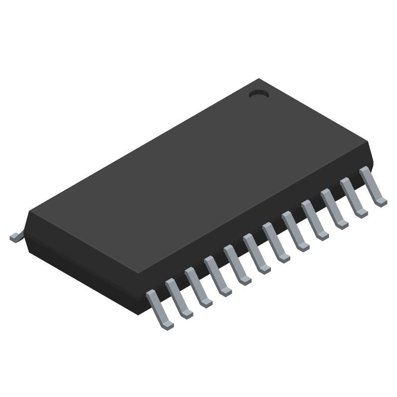
| Part Package Code | SOIC | |
| Package Description | Sop-24 | |
| Pin Count | 24 | |
| HTS Code | 8542.31.00.15 | |
| Has ADC | No | |
| Address Bus Width | ||
| Bit Size | 8 | |
| Boundary Scan | Yes | |
| CPU Family | St72 | |
| Clock Frequency-Max | 24 Mhz | |
| DAC Channels | No | |
| DMA Channels | Yes | |
| External Data Bus Width | ||
| JESD-30 Code | R-PDSO-G24 | |
| JESD-609 Code | e4 | |
| Length | 15.4 Mm | |
| Moisture Sensitivity Level | 3 | |
| Number of I/O Lines | 14 | |
| Number of Terminals | 24 | |
| On Chip Program ROM Width | 8 | |
| Operating Temperature-Max | 70 °C | |
| Operating Temperature-Min | ||
| PWM Channels | Yes | |
| Package Body Material | Plastic/Epoxy | |
| Package Code | SOP | |
| Package Equivalence Code | SOP24,.4 | |
| Package Shape | Rectangular | |
| Package Style | Small Outline | |
| Peak Reflow Temperature (Cel) | 250 | |
| Qualification Status | Not Qualified | |
| RAM (bytes) | 384 | |
| ROM (words) | 8192 | |
| ROM Programmability | Flash | |
| Seated Height-Max | 2.65 Mm | |
| Speed | 8 Mhz | |
| Supply Current-Max | 13 Ma | |
| Supply Voltage-Max | 5.5 V | |
| Supply Voltage-Min | 5 V | |
| Supply Voltage-Nom | 5 V | |
| Surface Mount | Yes | |
| Technology | Cmos | |
| Temperature Grade | Commercial | |
| Terminal Finish | Nickel/Palladium/Gold (Ni/Pd/Au) | |
| Terminal Form | Gull Wing | |
| Terminal Pitch | 1.27 Mm | |
| Terminal Position | Dual | |
| Time@Peak Reflow Temperature-Max (s) | 30 | |
| Width | 7.5 Mm | |
| uPs/uCs/Peripheral ICs Type | Microcontroller |
ST72F60E2M1 Frequently Asked Questions (FAQ)
-
The maximum clock frequency that can be used with the internal oscillator is 16 MHz. However, it's recommended to use a clock frequency of 12 MHz or lower to ensure reliable operation.
-
The watchdog timer can be configured using the WWDG_CR register. Set the WWDG_CR[WDGA] bit to enable the watchdog timer, and then set the WWDG_CR[7:0] bits to set the timeout period.
-
The maximum current that can be sourced or sunk by the GPIO pins is 20 mA. However, it's recommended to limit the current to 10 mA or less to ensure reliable operation.
-
To use the ADC with an external reference voltage, connect the external reference voltage to the VREF+ pin, and set the ADC_CSR[REFSEL] bit to 1. Then, configure the ADC channel and start the conversion using the ADC_CSR[START] bit.
-
The minimum voltage range for the VDD power supply is 2.4 V, and the maximum voltage range is 5.5 V.