-
Part Symbol
-
Footprint
-
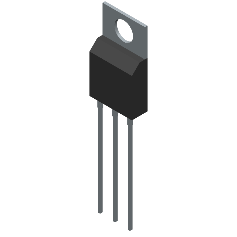
3D Model
Available Download Formats
By downloading CAD models, you agree to our Terms & Conditions and Privacy Policy

Insulated Gate Bipolar Transistor, 40A I(C), 600V V(BR)CES, N-Channel
Tip: Data for a part may vary between manufacturers. You can filter for manufacturers on the top of the page next to the part image and part number.
STGFW20V60F by STMicroelectronics is an IGBT.
IGBTs are under the broader part category of Transistors.
A transistor is a small semiconductor device used to amplify, control, or create electrical signals. When selecting a transistor, factors such as voltage, current rating, gain, and power dissipation must be considered, with common types. Read more about Transistors on our Transistors part category page.
| Part # | Distributor | Description | Stock | Price | Buy | |
|---|---|---|---|---|---|---|
|
DISTI #
497-13954-5-ND
|
DigiKey | IGBT TRENCH FS 600V 40A TO-3PF Min Qty: 1 Lead time: 20 Weeks Container: Tube |
281 In Stock |
|
$1.2523 / $2.8400 | Buy Now |
|
|
STMicroelectronics | Trench gate field-stop IGBT, V series 600 V, 20 A very high speed COO: South Korea RoHS: Compliant Min Qty: 1 | 443 |
|
$1.2400 / $2.7800 | Buy Now |
|
|
Bristol Electronics | Min Qty: 2 | 565 |
|
$1.0519 / $3.0054 | Buy Now |
|
|
Quest Components | 452 |
|
$1.3023 / $3.0054 | Buy Now | |
|
|
Quest Components | 452 |
|
$2.2021 / $4.0038 | Buy Now |
By downloading CAD models, you agree to our Terms & Conditions and Privacy Policy
|
|
STGFW20V60F
STMicroelectronics
Buy Now
Datasheet
|
Compare Parts:
STGFW20V60F
STMicroelectronics
Insulated Gate Bipolar Transistor, 40A I(C), 600V V(BR)CES, N-Channel
|
| Rohs Code | Yes | |
| Part Life Cycle Code | Obsolete | |
| Part Package Code | TO-3PF | |
| Package Description | Rohs Compliant, To-3pf, 3 Pin | |
| Pin Count | 2 | |
| Reach Compliance Code | Not Compliant | |
| ECCN Code | EAR99 | |
| Case Connection | Isolated | |
| Collector Current-Max (IC) | 40 A | |
| Collector-Emitter Voltage-Max | 600 V | |
| Configuration | Single With Built-In Diode | |
| JESD-30 Code | R-PSFM-T3 | |
| JESD-609 Code | e3 | |
| Number of Elements | 1 | |
| Number of Terminals | 3 | |
| Package Body Material | Plastic/Epoxy | |
| Package Shape | Rectangular | |
| Package Style | Flange Mount | |
| Polarity/Channel Type | N-Channel | |
| Surface Mount | No | |
| Terminal Finish | Matte Tin | |
| Terminal Form | Through-Hole | |
| Terminal Position | Single | |
| Transistor Application | Power Control | |
| Transistor Element Material | Silicon | |
| Turn-off Time-Nom (toff) | 173 Ns | |
| Turn-on Time-Nom (ton) | 49 Ns |
The maximum junction temperature (Tj) of the STGFW20V60F is 175°C, as specified in the datasheet. However, it's recommended to keep the junction temperature below 150°C for reliable operation and to prevent thermal runaway.
To calculate the power dissipation of the STGFW20V60F, you need to consider the voltage drop across the device, the current flowing through it, and the thermal resistance (Rth) from junction to ambient (Rth(j-a)). The power dissipation (Pd) can be calculated using the formula: Pd = (Vds * Ids) + (Rth(j-a) * Tj), where Vds is the drain-source voltage, Ids is the drain-source current, and Tj is the junction temperature.
The recommended gate drive voltage for the STGFW20V60F is between 10V and 15V, with a maximum gate-source voltage (Vgs) of 20V. A higher gate drive voltage can improve switching performance, but it also increases the risk of gate oxide damage.
Yes, the STGFW20V60F is suitable for high-frequency switching applications up to 100 kHz. However, you need to consider the device's switching losses, gate drive requirements, and thermal management to ensure reliable operation. It's recommended to consult the datasheet and application notes for more information on high-frequency operation.
To protect the STGFW20V60F from overvoltage and overcurrent, you can use a combination of voltage regulators, current sensors, and protection circuits. It's recommended to use a voltage clamp or a transient voltage suppressor (TVS) to limit the voltage across the device, and a current sense resistor or a current limiter to prevent overcurrent conditions.