-
Part Symbol
-
Footprint
-
3D Model
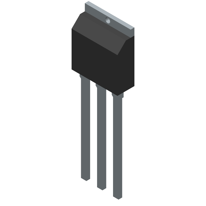
Available Download Formats
By downloading CAD models, you agree to our Terms & Conditions and Privacy Policy
Power Field-Effect Transistor, 2A I(D), 800V, 3.25ohm, 1-Element, N-Channel, Silicon, Metal-oxide Semiconductor FET, TO-251
Tip: Data for a part may vary between manufacturers. You can filter for manufacturers on the top of the page next to the part image and part number.
STU3LN80K5 by STMicroelectronics is a Power Field-Effect Transistor.
Power Field-Effect Transistors are under the broader part category of Transistors.
A transistor is a small semiconductor device used to amplify, control, or create electrical signals. When selecting a transistor, factors such as voltage, current rating, gain, and power dissipation must be considered, with common types. Read more about Transistors on our Transistors part category page.
| Part # | Distributor | Description | Stock | Price | Buy | |
|---|---|---|---|---|---|---|
|
DISTI #
497-17295-ND
|
DigiKey | MOSFET N-CHANNEL 800V 2A IPAK Min Qty: 1 Lead time: 14 Weeks Container: Tube |
2968 In Stock |
|
$0.4380 / $1.7500 | Buy Now |
|
DISTI #
STU3LN80K5
|
Avnet Americas | - Rail/Tube (Alt: STU3LN80K5) COO: Italy RoHS: Compliant Min Qty: 3000 Package Multiple: 3000 Lead time: 14 Weeks, 0 Days Container: Tube | 0 |
|
$0.4380 / $0.5006 | Buy Now |
|
DISTI #
511-STU3LN80K5
|
Mouser Electronics | MOSFETs N-channel 800 V, 2.75 Ohm typ., 2 A MDmesh K5 Power MOSFET in an IPAK package RoHS: Compliant | 1550 |
|
$0.4380 / $0.6300 | Buy Now |
|
|
STMicroelectronics | N-channel 800 V, 2.75 Ohm typ., 2 A MDmesh K5 Power MOSFET in an IPAK package COO: Italy RoHS: Compliant Min Qty: 1 | 1550 |
|
$0.4600 / $0.6200 | Buy Now |
|
|
Future Electronics | N-Channel 800 V 3.5 Ohm Through Hole MDmesh K5 Power Mosfet - IPAK RoHS: Compliant pbFree: Yes Min Qty: 3000 Package Multiple: 3000 Lead time: 14 Weeks Container: Tube | 0Tube |
|
$0.5000 / $0.5200 | Buy Now |
|
|
Future Electronics | N-Channel 800 V 3.5 Ohm Through Hole MDmesh K5 Power Mosfet - IPAK RoHS: Compliant pbFree: Yes Min Qty: 3000 Package Multiple: 3000 Lead time: 14 Weeks Container: Tube | 0Tube |
|
$0.5000 / $0.5700 | Buy Now |
|
DISTI #
STU3LN80K5
|
Avnet Silica | (Alt: STU3LN80K5) RoHS: Compliant Min Qty: 75 Package Multiple: 75 Lead time: 15 Weeks, 0 Days | Silica - 0 |
|
Buy Now |
By downloading CAD models, you agree to our Terms & Conditions and Privacy Policy
|
|
STU3LN80K5
STMicroelectronics
Buy Now
Datasheet
|
Compare Parts:
STU3LN80K5
STMicroelectronics
Power Field-Effect Transistor, 2A I(D), 800V, 3.25ohm, 1-Element, N-Channel, Silicon, Metal-oxide Semiconductor FET, TO-251
|
| Rohs Code | Yes | |
| Part Life Cycle Code | Active | |
| Package Description | Ipak-3 | |
| Manufacturer Package Code | IPAK | |
| Reach Compliance Code | Not Compliant | |
| ECCN Code | EAR99 | |
| Factory Lead Time | 14 Weeks | |
| Avalanche Energy Rating (Eas) | 155 Mj | |
| Case Connection | Drain | |
| Configuration | Single With Built-In Diode | |
| DS Breakdown Voltage-Min | 800 V | |
| Drain Current-Max (ID) | 2 A | |
| Drain-source On Resistance-Max | 3.25 Ω | |
| FET Technology | Metal-Oxide Semiconductor | |
| Feedback Cap-Max (Crss) | 0.1 Pf | |
| JEDEC-95 Code | TO-251 | |
| JESD-30 Code | R-PSIP-T3 | |
| Number of Elements | 1 | |
| Number of Terminals | 3 | |
| Operating Mode | Enhancement Mode | |
| Operating Temperature-Max | 150 °C | |
| Operating Temperature-Min | -55 °C | |
| Package Body Material | Plastic/Epoxy | |
| Package Shape | Rectangular | |
| Package Style | In-Line | |
| Peak Reflow Temperature (Cel) | Not Specified | |
| Polarity/Channel Type | N-Channel | |
| Power Dissipation-Max (Abs) | 45 W | |
| Pulsed Drain Current-Max (IDM) | 8 A | |
| Surface Mount | No | |
| Terminal Form | Through-Hole | |
| Terminal Position | Single | |
| Time@Peak Reflow Temperature-Max (s) | Not Specified | |
| Transistor Application | Switching | |
| Transistor Element Material | Silicon |
STMicroelectronics recommends a PCB layout with a thermal pad connected to a large copper area on the bottom layer, and multiple vias to dissipate heat efficiently.
To ensure reliable operation at high temperatures, it's essential to follow the recommended thermal design guidelines, use a suitable heat sink, and consider derating the device's power dissipation according to the temperature range.
To ensure EMI and EMC compliance, consider using a shielded layout, decoupling capacitors, and a common-mode choke. Additionally, follow the recommended PCB layout and component placement guidelines to minimize radiation and susceptibility.
Select input and output capacitors with a suitable voltage rating, capacitance value, and ESR (Equivalent Series Resistance) to ensure stable operation and minimize ripple voltage. Consult the datasheet and application notes for specific recommendations.
Increasing the switching frequency can improve efficiency, but it also increases switching losses and EMI radiation. A balance between efficiency and switching frequency must be found based on the specific application requirements.