Part Details for TLC5920DLRG4 by Texas Instruments
Results Overview of TLC5920DLRG4 by Texas Instruments
- Distributor Offerings: (2 listings)
- Number of FFF Equivalents: (0 replacements)
- Tariff Estimator: (Available) NEW
- Number of Functional Equivalents: (0 options)
- CAD Models: (Available)
- Part Data Attributes: (Available)
- Reference Designs: (Not Available)
Tip: Data for a part may vary between manufacturers. You can filter for manufacturers on the top of the page next to the part image and part number.
TLC5920DLRG4 Information
TLC5920DLRG4 by Texas Instruments is a Display Driver.
Display Drivers are under the broader part category of Drivers And Interfaces.
A driver controls the current or voltage delivered to components like LCDs or motors, while an interface component connects systems for data transfer and control. Read more about Drivers And Interfaces on our Drivers And Interfaces part category page.
Price & Stock for TLC5920DLRG4
| Part # | Distributor | Description | Stock | Price | Buy | |
|---|---|---|---|---|---|---|
|
DISTI #
TLC5920DLRG4-ND
|
DigiKey | IC LED DRIVER LINEAR 30MA 48SSOP Min Qty: 1000 Container: Tape & Reel |
0 Tape & Reel |
|
$1.2980 / $1.3815 | Buy Now |
|
|
Vyrian | LED Driver, 24-Segment, PDSO48 | 7020 |
|
RFQ |
US Tariff Estimator: TLC5920DLRG4 by Texas Instruments
Calculations from this tool are estimations only for imports into the United States. Please refer to the distributor or manufacturer and reference official US government sources and authorities to verify any final purchase costs.
TLC5920DLRG4 CAD Models
-
Part Symbol
-
Footprint
-
3D Model
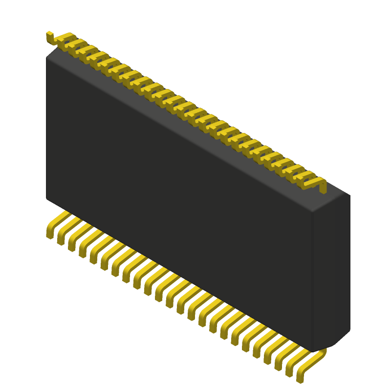
Available Download Formats
By downloading CAD models, you agree to our Terms & Conditions and Privacy Policy
TLC5920DLRG4 Part Data Attributes
|
|
TLC5920DLRG4
Texas Instruments
Buy Now
Datasheet
|
Compare Parts:
TLC5920DLRG4
Texas Instruments
LED Driver, 24-Segment, PDSO48
|
| Pbfree Code | Yes | |
| Rohs Code | Yes | |
| Part Life Cycle Code | Obsolete | |
| Part Package Code | SSOP | |
| Package Description | Green, Plastic, Ssop-48 | |
| Pin Count | 48 | |
| ECCN Code | EAR99 | |
| HTS Code | 8542.33.00.01 | |
| Additional Feature | Common-Cathode | |
| Data Input Mode | Serial | |
| Display Mode | Dot Matrix | |
| Input Characteristics | Standard | |
| Interface IC Type | Led Display Driver | |
| JESD-30 Code | R-PDSO-G48 | |
| JESD-609 Code | e4 | |
| Length | 15.875 Mm | |
| Moisture Sensitivity Level | 2 | |
| Multiplexed Display Capability | No | |
| Number of Functions | 1 | |
| Number of Segments | 24 | |
| Number of Terminals | 48 | |
| Operating Temperature-Max | 85 °C | |
| Operating Temperature-Min | -20 °C | |
| Output Characteristics | Constant-Current | |
| Package Body Material | Plastic/Epoxy | |
| Package Code | SSOP | |
| Package Equivalence Code | SSOP48,.4 | |
| Package Shape | Rectangular | |
| Package Style | Small Outline, Shrink Pitch | |
| Peak Reflow Temperature (Cel) | 260 | |
| Qualification Status | Not Qualified | |
| Seated Height-Max | 2.79 Mm | |
| Supply Current-Max | 1.6 Ma | |
| Supply Voltage-Max | 5.5 V | |
| Supply Voltage-Min | 4.5 V | |
| Supply Voltage-Nom | 5 V | |
| Surface Mount | Yes | |
| Temperature Grade | Other | |
| Terminal Finish | Nickel Palladium Gold | |
| Terminal Form | Gull Wing | |
| Terminal Pitch | 0.635 Mm | |
| Terminal Position | Dual | |
| Time@Peak Reflow Temperature-Max (s) | 30 | |
| Width | 7.5 Mm | |
| fmax-Min | 10 Mhz |
TLC5920DLRG4 Frequently Asked Questions (FAQ)
-
The TLC5920 can source up to 25mA and sink up to 50mA per output, but it's recommended to limit the current to 10mA per output for reliable operation.
-
The TLC5920 requires a power-on reset (POR) to ensure proper initialization. A 10uF capacitor between VCC and GND, and a 1kΩ resistor between VCC and SCL are recommended to ensure a clean power-up sequence.
-
The TLC5920 can handle I2C clock frequencies up to 400kHz, but it's recommended to limit the frequency to 100kHz for reliable operation.
-
The TLC5920 uses a 7-bit current register to program the LED current. The current is set using the I2C interface, and the register value is proportional to the desired current. A detailed calculation is provided in the datasheet.
-
The OE pin is used to enable or disable all outputs simultaneously. When OE is low, all outputs are enabled. When OE is high, all outputs are disabled. This pin can be used to quickly turn off all LEDs during power-down or reset conditions.