Part Details for BUF04701AIPWRG4 by Texas Instruments
Results Overview of BUF04701AIPWRG4 by Texas Instruments
- Distributor Offerings: (2 listings)
- Number of FFF Equivalents: (0 replacements)
- Tariff Estimator: (Available) NEW
- Number of Functional Equivalents: (0 options)
- CAD Models: (Available)
- Part Data Attributes: (Available)
- Reference Designs: (Not Available)
Tip: Data for a part may vary between manufacturers. You can filter for manufacturers on the top of the page next to the part image and part number.
BUF04701AIPWRG4 Information
BUF04701AIPWRG4 by Texas Instruments is a Buffer Amplifier.
Buffer Amplifiers are under the broader part category of Amplifier Circuits.
Amplifier circuits use external power to increase the amplitude of an input signal. They can be used to perform linear amplifications or logarithmic functions. Read more about Amplifier Circuits on our Amplifier Circuits part category page.
Price & Stock for BUF04701AIPWRG4
| Part # | Distributor | Description | Stock | Price | Buy | |
|---|---|---|---|---|---|---|
|
DISTI #
86094228
|
Verical | Buffer Amplifier 14-Pin TSSOP T/R RoHS: Compliant Min Qty: 311 Package Multiple: 1 Date Code: 0501 | Americas - 4000 |
|
$0.7494 / $1.2086 | Buy Now |
|
|
Rochester Electronics | Buffer Amplifier, 4 Func, CMOS, PDSO14 RoHS: Compliant Status: Obsolete Min Qty: 1 | 4000 |
|
$0.5995 / $0.9669 | Buy Now |
US Tariff Estimator: BUF04701AIPWRG4 by Texas Instruments
Calculations from this tool are estimations only for imports into the United States. Please refer to the distributor or manufacturer and reference official US government sources and authorities to verify any final purchase costs.
BUF04701AIPWRG4 CAD Models
-
Part Symbol
-
Footprint
-
3D Model
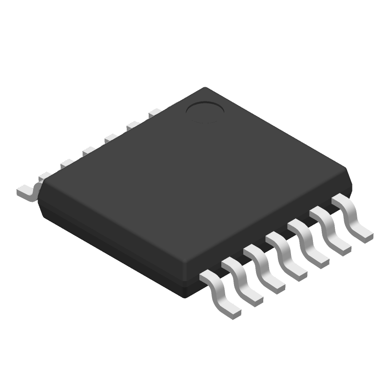
Available Download Formats
By downloading CAD models, you agree to our Terms & Conditions and Privacy Policy
BUF04701AIPWRG4 Part Data Attributes
|
|
BUF04701AIPWRG4
Texas Instruments
Buy Now
Datasheet
|
Compare Parts:
BUF04701AIPWRG4
Texas Instruments
Buffer Amplifier, 4 Func, CMOS, PDSO14
|
| Pbfree Code | Yes | |
| Rohs Code | Yes | |
| Part Life Cycle Code | Obsolete | |
| Part Package Code | TSSOP | |
| Package Description | Green, Plastic, Tssop-14 | |
| Pin Count | 14 | |
| ECCN Code | EAR99 | |
| HTS Code | 8542.33.00.01 | |
| Amplifier Type | Buffer | |
| Average Bias Current-Max (IIB) | 0.00001 µA | |
| Bandwidth (3dB)-Nom | 8 Mhz | |
| Bias Current-Max (IIB) @25C | 0.00001 µA | |
| Input Offset Voltage-Max | 7000 µV | |
| JESD-30 Code | R-PDSO-G14 | |
| JESD-609 Code | e4 | |
| Length | 5 Mm | |
| Moisture Sensitivity Level | 1 | |
| Neg Supply Voltage Limit-Max | -6.6 V | |
| Neg Supply Voltage-Nom (Vsup) | -5 V | |
| Number of Functions | 4 | |
| Number of Terminals | 14 | |
| Operating Temperature-Max | 125 °C | |
| Operating Temperature-Min | -40 °C | |
| Package Body Material | Plastic/Epoxy | |
| Package Code | TSSOP | |
| Package Equivalence Code | TSSOP14,.25 | |
| Package Shape | Rectangular | |
| Package Style | Small Outline, Thin Profile, Shrink Pitch | |
| Packing Method | Tr | |
| Peak Reflow Temperature (Cel) | 260 | |
| Qualification Status | Not Qualified | |
| Seated Height-Max | 1.2 Mm | |
| Slew Rate-Nom | 10 V/Us | |
| Supply Current-Max | 6.8 Ma | |
| Supply Voltage Limit-Max | 6.6 V | |
| Supply Voltage-Nom (Vsup) | 5 V | |
| Surface Mount | Yes | |
| Technology | Cmos | |
| Temperature Grade | Automotive | |
| Terminal Finish | Nickel Palladium Gold | |
| Terminal Form | Gull Wing | |
| Terminal Pitch | 0.65 Mm | |
| Terminal Position | Dual | |
| Time@Peak Reflow Temperature-Max (s) | 30 | |
| Width | 4.4 Mm |
BUF04701AIPWRG4 Frequently Asked Questions (FAQ)
-
Texas Instruments provides a recommended PCB layout in the datasheet, but it's essential to follow good PCB design practices, such as separating analog and digital grounds, using a solid ground plane, and placing decoupling capacitors close to the device. Additionally, ensure that the input and output traces are short and well-matched to minimize signal reflections.
-
The output capacitor value depends on the specific application requirements, such as output voltage, current, and ripple. A general rule of thumb is to use a capacitor with a value between 1uF to 10uF, with a voltage rating that exceeds the output voltage. However, it's recommended to consult the datasheet and application notes for more specific guidance.
-
The BUF04701AIPWRG4 has an absolute maximum input voltage rating of 6V. Exceeding this voltage can cause damage to the device. However, the recommended operating input voltage range is 2.7V to 5.5V.
-
The BUF04701AIPWRG4 is rated for operation up to 125°C (TJ). However, the device's performance and reliability may degrade at high temperatures. It's essential to consider the thermal management and ensure that the device operates within the recommended temperature range.
-
Proper biasing is critical for the BUF04701AIPWRG4. Ensure that the input voltage is within the recommended range, and the output voltage is set to the desired level using a resistive divider or other voltage-setting circuitry. Consult the datasheet and application notes for specific guidance on biasing and voltage-setting.