| Part Number | Manufacturer | Composite Price | Description | Compare |
|---|---|---|---|---|
| MAX211IDWRG4 | Texas Instruments | Check for Price | Line Transceiver, 4 Func, 4 Driver, 5 Rcvr, BICMOS, PDSO28 | MAX211IDWR vs MAX211IDWRG4 |
| MAX211CDWRE4 | Texas Instruments | Check for Price | Line Transceiver, 4 Func, 4 Driver, 5 Rcvr, BICMOS, PDSO28 | MAX211IDWR vs MAX211CDWRE4 |
| MAX211IDW | Texas Instruments | Check for Price | Line Transceiver, 4 Func, 4 Driver, 5 Rcvr, BICMOS, PDSO28 | MAX211IDWR vs MAX211IDW |
| MAX211CDWE4 | Texas Instruments | Check for Price | Line Transceiver, 4 Func, 4 Driver, 5 Rcvr, BICMOS, PDSO28 | MAX211IDWR vs MAX211CDWE4 |
| MAX211CDWRG4 | Texas Instruments | Check for Price | Line Transceiver, 4 Func, 4 Driver, 5 Rcvr, BICMOS, PDSO28 | MAX211IDWR vs MAX211CDWRG4 |
| MAX211IDWG4 | Texas Instruments | Check for Price | Line Transceiver, 4 Func, 4 Driver, 5 Rcvr, BICMOS, PDSO28 | MAX211IDWR vs MAX211IDWG4 |
| MAX211CDW | Texas Instruments | Check for Price | Line Transceiver, 4 Func, 4 Driver, 5 Rcvr, BICMOS, PDSO28 | MAX211IDWR vs MAX211CDW |
| MAX211IDWE4 | Texas Instruments | Check for Price | Line Transceiver, 4 Func, 4 Driver, 5 Rcvr, BICMOS, PDSO28 | MAX211IDWR vs MAX211IDWE4 |
| MAX211CDWG4 | Texas Instruments | Check for Price | Line Transceiver, 4 Func, 4 Driver, 5 Rcvr, BICMOS, PDSO28 | MAX211IDWR vs MAX211CDWG4 |
| MAX211IDWRE4 | Texas Instruments | Check for Price | Line Transceiver, 4 Func, 4 Driver, 5 Rcvr, BICMOS, PDSO28 | MAX211IDWR vs MAX211IDWRE4 |
Part Details for MAX211IDWR by Texas Instruments
Results Overview of MAX211IDWR by Texas Instruments
- Distributor Offerings: (4 listings)
- Number of FFF Equivalents: (10 replacements)
- Tariff Estimator: (Available) NEW
- Number of Functional Equivalents: (10 options)
- CAD Models: (Available)
- Part Data Attributes: (Available)
- Reference Designs: (Not Available)
Tip: Data for a part may vary between manufacturers. You can filter for manufacturers on the top of the page next to the part image and part number.
MAX211IDWR Information
MAX211IDWR by Texas Instruments is a Line Driver or Receiver.
Line Driver or Receivers are under the broader part category of Drivers And Interfaces.
A driver controls the current or voltage delivered to components like LCDs or motors, while an interface component connects systems for data transfer and control. Read more about Drivers And Interfaces on our Drivers And Interfaces part category page.
Price & Stock for MAX211IDWR
| Part # | Distributor | Description | Stock | Price | Buy | |
|---|---|---|---|---|---|---|
|
DISTI #
90936727
|
Verical | Quad Transmitter Quint Receiver RS-232 28-Pin SOIC T/R RoHS: Compliant Min Qty: 166 Package Multiple: 1 Date Code: 0701 | Americas - 200 |
|
$1.9125 / $2.2625 | Buy Now |
|
DISTI #
595-MAX211IDWR
|
Mouser Electronics | RS-232 Interface IC 5V MultiCh Line Driv er/Receiver A 595-M A 595-MAX211IDW RoHS: Compliant | 7 |
|
$2.0800 / $3.4400 | Buy Now |
|
|
Rochester Electronics | IC INTERFACE Transceiver RS232 120kbps 1.5V - 5.5V 28-SOIC T/R RoHS: Compliant Status: Active Min Qty: 1 | 200 |
|
$1.5300 / $1.9100 | Buy Now |
|
|
Vyrian | Line Transceiver, 4 Func, 4 Driver, 5 Rcvr, PDSO28 | 3855 |
|
RFQ |
US Tariff Estimator: MAX211IDWR by Texas Instruments
Calculations from this tool are estimations only for imports into the United States. Please refer to the distributor or manufacturer and reference official US government sources and authorities to verify any final purchase costs.
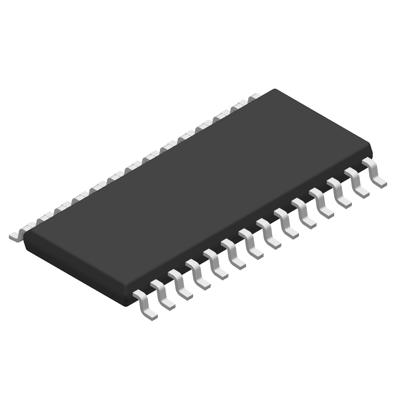
MAX211IDWR CAD Models
-
Part Symbol
-
Footprint
-
3D Model
Available Download Formats
By downloading CAD models, you agree to our Terms & Conditions and Privacy Policy
MAX211IDWR Part Data Attributes
|
|
MAX211IDWR
Texas Instruments
Buy Now
Datasheet
|
Compare Parts:
MAX211IDWR
Texas Instruments
Line Transceiver, 4 Func, 4 Driver, 5 Rcvr, BICMOS, PDSO28
|
| Pbfree Code | Yes | |
| Rohs Code | Yes | |
| Part Life Cycle Code | Active | |
| Part Package Code | SOIC | |
| Package Description | Soic-28 | |
| Pin Count | 28 | |
| ECCN Code | EAR99 | |
| HTS Code | 8542.39.00.90 | |
| Differential Output | No | |
| Driver Number of Bits | 4 | |
| High Level Input Current-Max | 0.0002 A | |
| Input Characteristics | Schmitt Trigger | |
| Interface IC Type | Line Transceiver | |
| Interface Standard | Eia-232-F; Tia-232-F; V.28 | |
| JESD-30 Code | R-PDSO-G28 | |
| JESD-609 Code | e4 | |
| Length | 17.9 Mm | |
| Moisture Sensitivity Level | 1 | |
| Number of Functions | 4 | |
| Number of Terminals | 28 | |
| Operating Temperature-Max | 85 °C | |
| Operating Temperature-Min | -40 °C | |
| Out Swing-Min | 10 V | |
| Output Characteristics | 3-State | |
| Output Low Current-Max | 0.0016 A | |
| Output Polarity | Inverted | |
| Package Body Material | Plastic/Epoxy | |
| Package Code | SOP | |
| Package Equivalence Code | SOP28,.4 | |
| Package Shape | Rectangular | |
| Package Style | Small Outline | |
| Peak Reflow Temperature (Cel) | 260 | |
| Qualification Status | Not Qualified | |
| Receive Delay-Max | 1000 Ns | |
| Receiver Number of Bits | 5 | |
| Seated Height-Max | 2.65 Mm | |
| Supply Current-Max | 20 Ma | |
| Supply Voltage-Max | 5.5 V | |
| Supply Voltage-Min | 4.5 V | |
| Supply Voltage-Nom | 5 V | |
| Supply Voltage1-Max | 5.5 V | |
| Supply Voltage1-Min | 4.5 V | |
| Supply Voltage1-Nom | 5 V | |
| Surface Mount | Yes | |
| Technology | Bicmos | |
| Temperature Grade | Industrial | |
| Terminal Finish | Nickel/Palladium/Gold (Ni/Pd/Au) | |
| Terminal Form | Gull Wing | |
| Terminal Pitch | 1.27 Mm | |
| Terminal Position | Dual | |
| Time@Peak Reflow Temperature-Max (s) | 30 | |
| Width | 7.5 Mm |
Alternate Parts for MAX211IDWR
This table gives cross-reference parts and alternative options found for MAX211IDWR. The Form Fit Function (FFF) tab will give you the options that are more likely to serve as direct pin-to-pin alternates or drop-in parts. The Functional Equivalents tab will give you options that are likely to match the same function of MAX211IDWR, but it may not fit your design. Always verify details of parts you are evaluating, as these parts are offered as suggestions for what you are looking for and are not guaranteed.
MAX211IDWR Frequently Asked Questions (FAQ)
-
Texas Instruments recommends a 4-layer PCB with a solid ground plane, and placing the device close to the power supply and away from noise sources. A good layout practice is to keep the analog and digital grounds separate and connect them at a single point.
-
To optimize performance in a noisy environment, use a low-pass filter on the input, keep the device away from noise sources, and use a shielded enclosure. Additionally, use a low-ESR capacitor on the VCC pin and a 0.1uF capacitor on the AVCC pin to filter out noise.
-
The MAX211IDWR is rated for operation from -40°C to 125°C, but the device's performance may degrade at extreme temperatures. It's recommended to operate the device within the -20°C to 85°C range for optimal performance.
-
The MAX211IDWR requires a power-up sequence to ensure proper initialization. Apply power to the VCC pin first, followed by the AVCC pin. The device will then initialize and be ready for operation.
-
The recommended input impedance for the MAX211IDWR is 50 ohms or less to ensure optimal performance and minimize signal reflections.