Tip: Data for a part may vary between manufacturers. You can filter for manufacturers on the top of the page next to the part image and part number.
ApplicationsConsumer ElectronicsEducation and ResearchInternet of Things (IoT)Computing and Data StorageAerospace and DefenseHealthcareTelecommunicationsAutomotive
TLC372CP Information
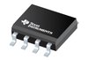
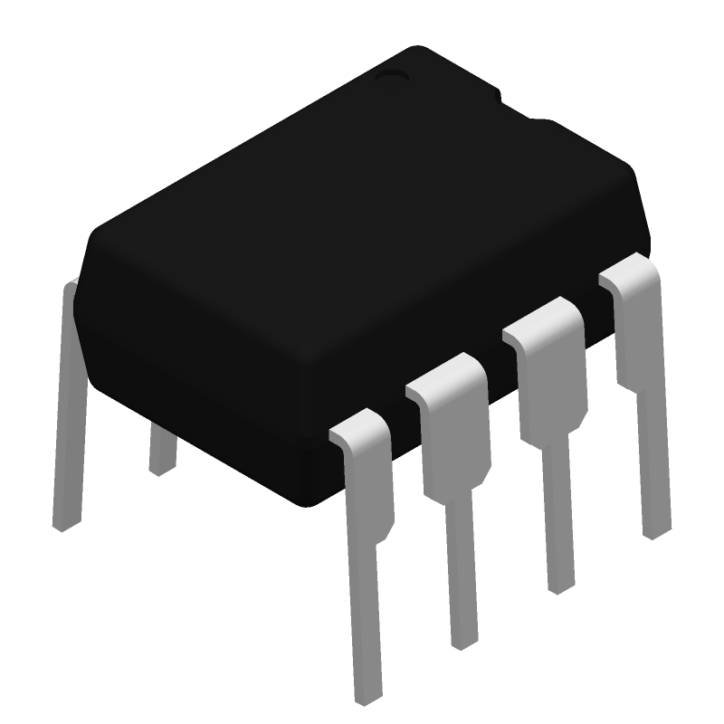
TLC372CP by Texas Instruments is a Comparator.
Comparators are under the broader part category of Amplifier Circuits.
Amplifier circuits use external power to increase the amplitude of an input signal. They can be used to perform linear amplifications or logarithmic functions. Read more about Amplifier Circuits on our Amplifier Circuits part category page.
US Tariff Estimator: TLC372CP by Texas Instruments
Calculations from this tool are estimations only for imports into the United States. Please refer to the distributor or manufacturer and reference official US government sources and authorities to verify any final purchase costs.
This table gives cross-reference parts and alternative options found for TLC372CP. The Form Fit Function (FFF) tab will give you the options that are more likely to serve as direct pin-to-pin alternates or drop-in parts. The Functional Equivalents tab will give you options that are likely to match the same function of TLC372CP, but it may not fit your design. Always verify details of parts you are evaluating, as these parts are offered as suggestions for what you are looking for and are not guaranteed.
The recommended operating voltage range for TLC372CP is 4.5V to 16V.
To ensure proper biasing, connect the non-inverting input (V+ or V-) to a voltage midpoint between the supply rails, and the inverting input (V-) to a voltage equal to the desired output voltage.
The maximum output current of the TLC372CP is 20mA.
To reduce noise and oscillations, use a bypass capacitor (e.g., 0.1uF) between the supply pins (VCC and GND), and consider adding a noise-reducing capacitor (e.g., 10nF) between the output and GND.
Yes, the TLC372CP can be used as a comparator by connecting the inverting input (V-) to a reference voltage and the non-inverting input (V+) to the signal to be compared.