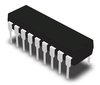
Part Details for L4963W by STMicroelectronics
Results Overview of L4963W by STMicroelectronics
- Distributor Offerings: (5 listings)
- Number of FFF Equivalents: (0 replacements)
- Tariff Estimator: (Available) NEW
- Number of Functional Equivalents: (0 options)
- CAD Models: (Available)
- Part Data Attributes: (Available)
- Reference Designs: (Not Available)
Tip: Data for a part may vary between manufacturers. You can filter for manufacturers on the top of the page next to the part image and part number.
L4963W Information
L4963W by STMicroelectronics is a Switching Regulator or Controller.
Switching Regulator or Controllers are under the broader part category of Power Circuits.
A power circuit delivers electricity in order to operate a load for an electronic device. Power circuits include transformers, generators and switches. Read more about Power Circuits on our Power Circuits part category page.
Price & Stock for L4963W
| Part # | Distributor | Description | Stock | Price | Buy | |
|---|---|---|---|---|---|---|
|
DISTI #
497-6696-5-ND
|
DigiKey | IC REG BUCK ADJ 1.5A 18DIP Min Qty: 1000 Container: Tube |
0 Tube |
|
$2.2843 | Buy Now |
|
DISTI #
L4963W
|
Avnet Americas | Conv DC-DC Single Step Down 9V to 46V 18-Pin Power PDIP - Rail/Tube (Alt: L4963W) COO: Malaysia RoHS: Compliant Min Qty: 1000 Package Multiple: 1000 Container: Tube | 0 |
|
RFQ | |
|
|
ComSIT USA | 1.5A SWITCHING REGULATOR Switching Regulator, Voltage-mode, 6.5A, 83kHz Switching Freq-Max, BIPolar, PDIP18 ECCN: EAR99 RoHS: Not Compliant |
|
|
RFQ | |
|
|
Chip Stock | L4963 Series 46 V 1.5 A 83 kHz Buck Through Hole Switching Regulator POWERDIP-18 | 10674 |
|
RFQ | |
|
|
Vyrian | Switching Regulator, Voltage-mode, 6.5A, 83kHz Switching Freq-Max, BIPolar, PDIP18 | 3891 |
|
RFQ |
US Tariff Estimator: L4963W by STMicroelectronics
Calculations from this tool are estimations only for imports into the United States. Please refer to the distributor or manufacturer and reference official US government sources and authorities to verify any final purchase costs.
L4963W CAD Models
-
Part Symbol
-
Footprint
-
3D Model
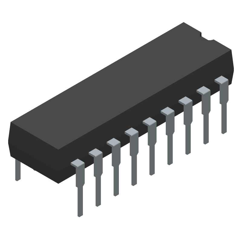
Available Download Formats
By downloading CAD models, you agree to our Terms & Conditions and Privacy Policy
L4963W Part Data Attributes
|
|
L4963W
STMicroelectronics
Buy Now
Datasheet
|
Compare Parts:
L4963W
STMicroelectronics
Switching Regulator, Voltage-mode, 6.5A, 83kHz Switching Freq-Max, BIPolar, PDIP18
|
| Rohs Code | Yes | |
| Part Life Cycle Code | Obsolete | |
| Part Package Code | DIP | |
| Package Description | Power, Plastic, Dip-18 | |
| Pin Count | 18 | |
| ECCN Code | EAR99 | |
| HTS Code | 8542.39.00.60 | |
| Date Of Intro | 1980-01-04 | |
| Analog IC - Other Type | Switching Regulator | |
| Control Mode | Voltage-Mode | |
| Control Technique | Pulse Frequency Modulation | |
| Input Voltage-Max | 46 V | |
| Input Voltage-Min | 9 V | |
| Input Voltage-Nom | 30 V | |
| JESD-30 Code | R-PDIP-T18 | |
| JESD-609 Code | e3 | |
| Length | 24.8 Mm | |
| Number of Functions | 1 | |
| Number of Terminals | 18 | |
| Operating Temperature-Max | 150 °C | |
| Operating Temperature-Min | -40 °C | |
| Output Current-Max | 6.5 A | |
| Output Voltage-Max | 36 V | |
| Output Voltage-Min | 5.1 V | |
| Package Body Material | Plastic/Epoxy | |
| Package Code | DIP | |
| Package Equivalence Code | DIP18,.3 | |
| Package Shape | Rectangular | |
| Package Style | In-Line | |
| Qualification Status | Not Qualified | |
| Seated Height-Max | 5.1 Mm | |
| Surface Mount | No | |
| Switcher Configuration | Buck | |
| Switching Frequency-Max | 83 Khz | |
| Technology | Bipolar | |
| Temperature Grade | Automotive | |
| Terminal Finish | Matte Tin | |
| Terminal Form | Through-Hole | |
| Terminal Pitch | 2.54 Mm | |
| Terminal Position | Dual | |
| Width | 7.62 Mm |
L4963W Frequently Asked Questions (FAQ)
-
The L4963W can handle an input voltage up to 40V, but it's recommended to keep it below 36V for reliable operation.
-
The inductor value depends on the output voltage, output current, and switching frequency. A good starting point is to use the inductor value calculation formula provided in the datasheet, and then adjust based on the specific design requirements.
-
The EN (enable) pin is used to turn the converter on and off. It's an active-high input, so connect it to a logic high (e.g., VCC) to enable the converter, and connect it to a logic low (e.g., GND) to disable it.
-
Ensure good thermal design, including a suitable PCB layout, thermal vias, and a heat sink if necessary. Monitor the junction temperature using the thermal monitoring pin (TMP) and adjust the design as needed to keep the temperature within the recommended range (-40°C to 150°C).
-
Follow the recommended layout and placement guidelines in the datasheet, including keeping the input and output capacitors close to the IC, and using a solid ground plane to reduce noise and improve thermal performance.