Part Details for MAX25400GTC/V+ by Analog Devices Inc
Results Overview of MAX25400GTC/V+ by Analog Devices Inc
- Distributor Offerings: (2 listings)
- Number of FFF Equivalents: (0 replacements)
- Tariff Estimator: (Available) NEW
- Number of Functional Equivalents: (0 options)
- CAD Models: (Available)
- Part Data Attributes: (Available)
- Reference Designs: (Not Available)
Tip: Data for a part may vary between manufacturers. You can filter for manufacturers on the top of the page next to the part image and part number.
MAX25400GTC/V+ Information
MAX25400GTC/V+ by Analog Devices Inc is a Power Management Circuit.
Power Management Circuits are under the broader part category of Power Circuits.
A power circuit delivers electricity in order to operate a load for an electronic device. Power circuits include transformers, generators and switches. Read more about Power Circuits on our Power Circuits part category page.
Price & Stock for MAX25400GTC/V+
| Part # | Distributor | Description | Stock | Price | Buy | |
|---|---|---|---|---|---|---|
|
DISTI #
83AH9956
|
Newark | High Speed Protector, Aec-Q100, 105Deg C Rohs Compliant: Yes |Analog Devices MAX25400GTC/V+ RoHS: Compliant Min Qty: 1 Package Multiple: 1 Date Code: 1 Container: Bulk | 0 |
|
Buy Now | |
|
|
Analog Devices Inc | 25mA-500mA Automotive Hi-Speed Package Multiple: 1 | 2573 |
|
Buy Now |
US Tariff Estimator: MAX25400GTC/V+ by Analog Devices Inc
Calculations from this tool are estimations only for imports into the United States. Please refer to the distributor or manufacturer and reference official US government sources and authorities to verify any final purchase costs.
Part Details for MAX25400GTC/V+
MAX25400GTC/V+ CAD Models
-
Part Symbol
-
Footprint
-
3D Model
Available Download Formats
By downloading CAD models, you agree to our Terms & Conditions and Privacy Policy
MAX25400GTC/V+ Part Data Attributes
|
|
MAX25400GTC/V+
Analog Devices Inc
Buy Now
Datasheet
|
Compare Parts:
MAX25400GTC/V+
Analog Devices Inc
Power Supply Support Circuit
|
| Rohs Code | Yes | |
| Part Life Cycle Code | Active | |
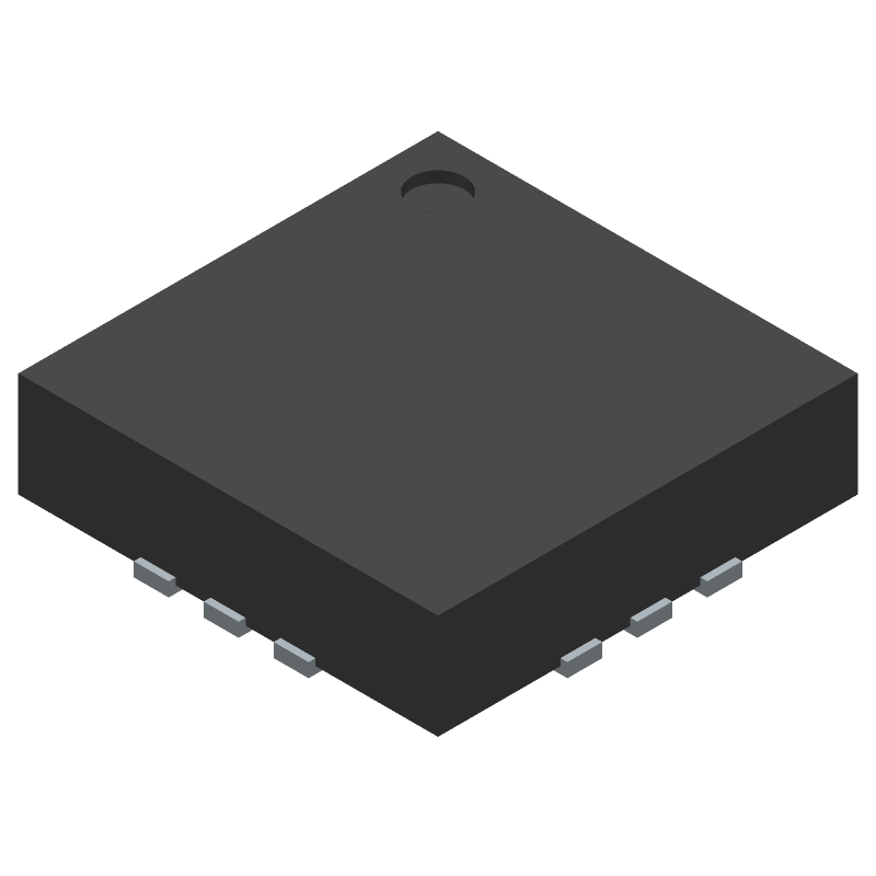
| Part Package Code | 12-LFCSP-3X3X0.75 | |
| Package Description | , | |
| Pin Count | 12 | |
| Manufacturer Package Code | 12-LFCSP-3X3X0.75 | |
| Reach Compliance Code | Compliant | |
| ECCN Code | EAR99 | |
| HTS Code | 8542.39.00.01 | |
| Date Of Intro | 2020-08-27 | |
| Analog IC - Other Type | Usb Pd Controller | |
| JESD-609 Code | e3 | |
| Moisture Sensitivity Level | 1 | |
| Peak Reflow Temperature (Cel) | 260 | |
| Terminal Finish | Matte Tin (Sn) - Annealed | |
| Time@Peak Reflow Temperature-Max (s) | 30 |
MAX25400GTC/V+ Frequently Asked Questions (FAQ)
-
A good PCB layout for the MAX25400GTC/V+ involves keeping the input and output traces short and away from each other, using a solid ground plane, and placing decoupling capacitors close to the device. A 4-layer PCB with a dedicated power plane and a dedicated ground plane is recommended. Additionally, it's essential to follow the layout guidelines provided in the datasheet and application notes.
-
The output voltage of the MAX25400GTC/V+ can be adjusted using the VOUT pin. To select the correct output voltage, you need to connect a resistive divider network between the VOUT pin and the GND pin. The ratio of the resistors determines the output voltage. You can use the formula provided in the datasheet to calculate the required resistor values for your desired output voltage.
-
The MAX25400GTC/V+ can handle input voltages up to 40V. However, it's recommended to operate the device within the specified input voltage range of 4.5V to 36V to ensure optimal performance and reliability.
-
To ensure the MAX25400GTC/V+ is stable and doesn't oscillate, you need to follow the recommended layout guidelines, use a sufficient output capacitor, and ensure that the input voltage is within the specified range. Additionally, you can add a small ceramic capacitor (e.g., 10nF) between the VOUT pin and the GND pin to improve stability.
-
The MAX25400GTC/V+ is rated for operation up to 125°C. However, the device's performance and reliability may degrade at high temperatures. It's essential to follow the recommended operating conditions and derate the device's performance accordingly. You may also need to consider using a heat sink or thermal management techniques to keep the device within its specified operating temperature range.