| Part Number | Manufacturer | Composite Price | Description | Compare |
|---|---|---|---|---|
| OPA2107AP | Texas Instruments | Check for Price | Operational Amplifier, 2 Func, 2000uV Offset-Max, BIPolar, PDIP8 | OPA2107APG4 vs OPA2107AP |
Part Details for OPA2107APG4 by Texas Instruments
Results Overview of OPA2107APG4 by Texas Instruments
- Distributor Offerings: (1 listing)
- Number of FFF Equivalents: (1 replacement)
- Tariff Estimator: (Available) NEW
- Number of Functional Equivalents: (5 options)
- CAD Models: (Available)
- Part Data Attributes: (Available)
- Reference Designs: (Not Available)
Tip: Data for a part may vary between manufacturers. You can filter for manufacturers on the top of the page next to the part image and part number.
Applications
Education and Research
Internet of Things (IoT)
Computing and Data Storage
Aerospace and Defense
Healthcare
Telecommunications
Automotive
OPA2107APG4 Information
OPA2107APG4 by Texas Instruments is an Operational Amplifier.
Operational Amplifiers are under the broader part category of Amplifier Circuits.
Amplifier circuits use external power to increase the amplitude of an input signal. They can be used to perform linear amplifications or logarithmic functions. Read more about Amplifier Circuits on our Amplifier Circuits part category page.
Price & Stock for OPA2107APG4
| Part # | Distributor | Description | Stock | Price | Buy | |
|---|---|---|---|---|---|---|
|
|
Vyrian | Operational Amplifier, 2 Func, 2000uV Offset-Max, BIPolar, PDIP8 | 9567 |
|
RFQ |
US Tariff Estimator: OPA2107APG4 by Texas Instruments
Calculations from this tool are estimations only for imports into the United States. Please refer to the distributor or manufacturer and reference official US government sources and authorities to verify any final purchase costs.
OPA2107APG4 CAD Models
-
Part Symbol
-
Footprint
-
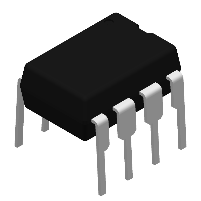
3D Model
Available Download Formats
By downloading CAD models, you agree to our Terms & Conditions and Privacy Policy
OPA2107APG4 Part Data Attributes
|
|
OPA2107APG4
Texas Instruments
Buy Now
Datasheet
|
Compare Parts:
OPA2107APG4
Texas Instruments
Operational Amplifier, 2 Func, 2000uV Offset-Max, BIPolar, PDIP8
|
| Pbfree Code | Yes | |
| Rohs Code | Yes | |
| Part Life Cycle Code | Obsolete | |
| Part Package Code | DIP | |
| Package Description | Dip-8 | |
| Pin Count | 8 | |
| ECCN Code | EAR99 | |
| HTS Code | 8542.33.00.01 | |
| Amplifier Type | Operational Amplifier | |
| Architecture | Voltage-Feedback | |
| Average Bias Current-Max (IIB) | 0.0015 µA | |
| Bias Current-Max (IIB) @25C | 0.00001 µA | |
| Common-mode Reject Ratio-Min | 80 Db | |
| Common-mode Reject Ratio-Nom | 94 Db | |
| Frequency Compensation | Yes | |
| Input Offset Current-Max (IIO) | 0.001 µA | |
| Input Offset Voltage-Max | 2000 µV | |
| JESD-30 Code | R-PDIP-T8 | |
| JESD-609 Code | e4 | |
| Length | 9.59 Mm | |
| Low-Bias | Yes | |
| Low-Offset | No | |
| Micropower | No | |
| Neg Supply Voltage Limit-Max | -18 V | |
| Neg Supply Voltage-Nom (Vsup) | -15 V | |
| Number of Functions | 2 | |
| Number of Terminals | 8 | |
| Operating Temperature-Max | 85 °C | |
| Operating Temperature-Min | -25 °C | |
| Package Body Material | Plastic/Epoxy | |
| Package Code | DIP | |
| Package Equivalence Code | DIP8,.3 | |
| Package Shape | Rectangular | |
| Package Style | In-Line | |
| Packing Method | Tube | |
| Power | Yes | |
| Programmable Power | No | |
| Qualification Status | Not Qualified | |
| Seated Height-Max | 5.08 Mm | |
| Slew Rate-Min | 13 V/Us | |
| Slew Rate-Nom | 18 V/Us | |
| Supply Voltage Limit-Max | 18 V | |
| Supply Voltage-Nom (Vsup) | 15 V | |
| Surface Mount | No | |
| Technology | Bipolar | |
| Temperature Grade | Other | |
| Terminal Finish | Nickel/Palladium/Gold (Ni/Pd/Au) | |
| Terminal Form | Through-Hole | |
| Terminal Pitch | 2.54 Mm | |
| Terminal Position | Dual | |
| Unity Gain BW-Nom | 4500 | |
| Voltage Gain-Min | 10000 | |
| Wideband | No | |
| Width | 7.62 Mm |
Alternate Parts for OPA2107APG4
This table gives cross-reference parts and alternative options found for OPA2107APG4. The Form Fit Function (FFF) tab will give you the options that are more likely to serve as direct pin-to-pin alternates or drop-in parts. The Functional Equivalents tab will give you options that are likely to match the same function of OPA2107APG4, but it may not fit your design. Always verify details of parts you are evaluating, as these parts are offered as suggestions for what you are looking for and are not guaranteed.
OPA2107APG4 Frequently Asked Questions (FAQ)
-
Texas Instruments provides a recommended PCB layout in the datasheet, which includes guidelines for component placement, trace routing, and grounding. Additionally, it's essential to follow good PCB design practices, such as minimizing noise coupling, using a solid ground plane, and keeping signal traces short and direct.
-
The choice of gain resistors depends on the desired gain, bandwidth, and noise requirements. The OPA2107APG4 datasheet provides a gain resistor selection table, and Texas Instruments also offers online tools, such as the Op-Amp Gain Calculator, to help with resistor selection. Additionally, consider the resistor's tolerance, temperature coefficient, and parasitic capacitance when making your selection.
-
The maximum power dissipation for the OPA2107APG4 is dependent on the ambient temperature and the package type. The datasheet specifies a maximum power dissipation of 1.4W for the PG4 package, but this can be derated based on the ambient temperature. It's essential to calculate the power dissipation for your specific application and ensure it's within the recommended limits to prevent overheating and reliability issues.
-
To protect the OPA2107APG4 from EMI, use proper shielding, grounding, and layout techniques. Keep the op-amp and its associated components away from noise sources, such as switching power supplies and high-frequency circuits. Use a shielded enclosure, and consider adding EMI filters or common-mode chokes to reduce noise coupling. Additionally, follow good PCB design practices, such as using a solid ground plane and minimizing loop areas.
-
The OPA2107APG4 datasheet recommends keeping the input capacitance below 10pF to maintain stability and minimize oscillations. For the output, a capacitance of 10nF to 100nF is recommended to improve stability and reduce ringing. However, the optimal capacitance values may vary depending on the specific application and circuit configuration.