-
3D Model
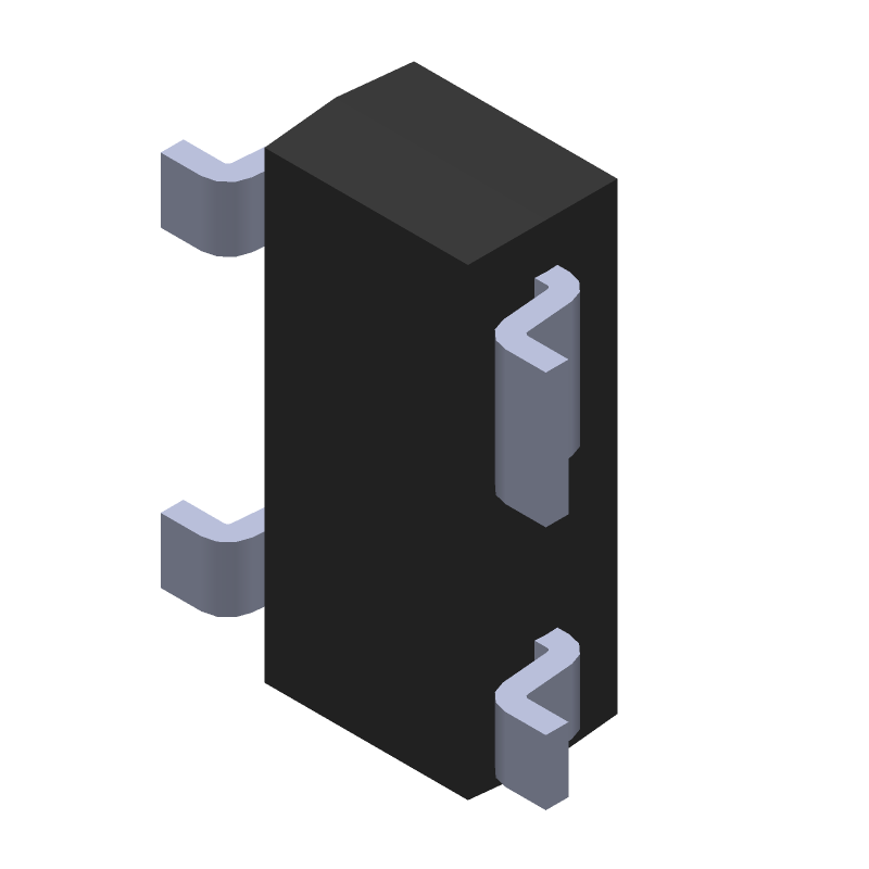
Available Download Formats
By downloading CAD models, you agree to our Terms & Conditions and Privacy Policy
Transistor
Tip: Data for a part may vary between manufacturers. You can filter for manufacturers on the top of the page next to the part image and part number.
SST215-LF by Calogic Inc is a Small Signal Field-Effect Transistor.
Small Signal Field-Effect Transistors are under the broader part category of Transistors.
A transistor is a small semiconductor device used to amplify, control, or create electrical signals. When selecting a transistor, factors such as voltage, current rating, gain, and power dissipation must be considered, with common types. Read more about Transistors on our Transistors part category page.
| Part # | Distributor | Description | Stock | Price | Buy | |
|---|---|---|---|---|---|---|
|
|
Future Electronics | SST215 Series Fast DMOS FET Switches N-Ch Enhancement-Mode - SOT-143 RoHS: Compliant pbFree: Yes Min Qty: 2500 Package Multiple: 2500 Lead time: 8 Weeks Container: Reel | 0Reel |
|
$2.2000 | Buy Now |
|
|
Quest Components | 50 MA, 20 V, N-CHANNEL, SI, SMALL SIGNAL, MOSFET | 320 |
|
$1.9530 / $4.8825 | Buy Now |
|
|
Karl Kruse GmbH & Co KG | Trans MOSFET N-CH 20V 0.05A 4-Pin(3+Tab) SOT-143 | 2500 |
|
RFQ | |
|
|
Karl Kruse GmbH & Co KG | Trans MOSFET N-CH 20V 0.05A 4-Pin(3+Tab) SOT-143 | 240 |
|
RFQ | |
|
|
NAC | SST215 Series Fast DMOS FET Switches N-Ch Enhancement-Mode - SOT-143 RoHS: Compliant Min Qty: 2500 Package Multiple: 2500 | 0 |
|
$2.3300 / $2.5800 | Buy Now |
By downloading CAD models, you agree to our Terms & Conditions and Privacy Policy
|
|
SST215-LF
Calogic Inc
Buy Now
Datasheet
|
Compare Parts:
SST215-LF
Calogic Inc
Transistor
|
| Rohs Code | Yes | |
| Part Life Cycle Code | Active | |
| Package Description | Sot-143, 3 Pin | |
| Reach Compliance Code | Compliant | |
| ECCN Code | EAR99 | |
| Configuration | Single With Built-In Diode | |
| DS Breakdown Voltage-Min | 20 V | |
| Drain Current-Max (ID) | 0.05 A | |
| Drain-source On Resistance-Max | 70 Ω | |
| FET Technology | Metal-Oxide Semiconductor | |
| Feedback Cap-Max (Crss) | 0.5 Pf | |
| JESD-30 Code | R-PDSO-G4 | |
| Number of Elements | 1 | |
| Number of Terminals | 4 | |
| Operating Mode | Enhancement Mode | |
| Operating Temperature-Max | 125 °C | |
| Operating Temperature-Min | -55 °C | |
| Package Body Material | Unspecified | |
| Package Shape | Rectangular | |
| Package Style | Small Outline | |
| Polarity/Channel Type | N-Channel | |
| Power Dissipation-Max (Abs) | 0.36 W | |
| Surface Mount | Yes | |
| Terminal Form | Gull Wing | |
| Terminal Position | Dual | |
| Transistor Application | Switching | |
| Transistor Element Material | Silicon |
A thermal pad on the bottom of the package should be connected to a large copper area on the PCB to dissipate heat. A minimum of 2oz copper thickness is recommended.
The device requires a stable input voltage and a bias current of 10mA to 50mA for optimal performance. A voltage regulator and a current-limiting resistor can be used to achieve this.
A 10uF to 22uF ceramic capacitor is recommended for input decoupling to reduce noise and ensure stable operation.
The device is rated for operation up to 125°C, but derating is required above 85°C. Consult the datasheet for specific derating guidelines.
Use a voltage clamp or a transient voltage suppressor (TVS) to protect against overvoltage. A current-limiting resistor or a fuse can be used to protect against overcurrent.