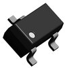
| Part Number | Manufacturer | Composite Price | Description | Compare |
|---|---|---|---|---|
| SST511 | Vishay Siliconix | Check for Price | Current Regulator Diode, 3.8mA I(S), 4.2V V(L), Silicon | SST511 vs SST511 |
| SST511-E3 | Vishay Siliconix | Check for Price | Current Regulator Diode, 4.7mA I(S), 4.2V V(L), Silicon, TO-236AB | SST511 vs SST511-E3 |
| SST511 | Calogic Inc | Check for Price | Current Regulator Diode, 4.7mA I(S), 4.2V V(L), Silicon | SST511 vs SST511 |
Part Details for SST511 by Linear Integrated Systems
Results Overview of SST511 by Linear Integrated Systems
- Distributor Offerings: (0 listings)
- Number of FFF Equivalents: (3 replacements)
- Tariff Estimator: (Available) NEW
- Number of Functional Equivalents: (3 options)
- CAD Models: (Request Part)
- Part Data Attributes: (Available)
- Reference Designs: (Not Available)
Tip: Data for a part may vary between manufacturers. You can filter for manufacturers on the top of the page next to the part image and part number.
Applications
Education and Research
Environmental Monitoring
Industrial Automation
Transportation and Logistics
Agriculture Technology
Electronic Manufacturing
Renewable Energy
Automotive
Robotics and Drones
SST511 Information
SST511 by Linear Integrated Systems is a Current Regulator Diode.
Current Regulator Diodes are under the broader part category of Diodes.
A diode is a electrical part that can control the direction in which the current flows in a device. Consider factors like voltage drop, current capacity, reverse voltage, and operating frequency when selecting a diode. Read more about Diodes on our Diodes part category page.
US Tariff Estimator: SST511 by Linear Integrated Systems
Calculations from this tool are estimations only for imports into the United States. Please refer to the distributor or manufacturer and reference official US government sources and authorities to verify any final purchase costs.
SST511 Part Data Attributes
|
|
SST511
Linear Integrated Systems
Buy Now
Datasheet
|
Compare Parts:
SST511
Linear Integrated Systems
Current Regulator Diode, 4.7mA I(S), 2.1V V(L), Silicon
|
| Pbfree Code | Yes | |
| Rohs Code | Yes | |
| Part Life Cycle Code | Active | |
| Part Package Code | SOT-23 | |
| Pin Count | 3 | |
| ECCN Code | EAR99 | |
| HTS Code | 8541.10.00.70 | |
| Configuration | Single | |
| Diode Element Material | Silicon | |
| Diode Type | Current Regulator Diode | |
| Dynamic Impedance-Min | 200000 Ω | |
| JESD-30 Code | R-PDSO-G3 | |
| Limiting Voltage-Max | 2.1 V | |
| Number of Elements | 1 | |
| Number of Terminals | 3 | |
| Operating Temperature-Max | 135 °C | |
| Operating Temperature-Min | -55 °C | |
| Package Body Material | Plastic/Epoxy | |
| Package Shape | Rectangular | |
| Package Style | Small Outline | |
| Peak Reflow Temperature (Cel) | 260 | |
| Power Dissipation-Max | 0.35 W | |
| Qualification Status | Not Qualified | |
| Regulation Current-Nom (Ireg) | 4.7 Ma | |
| Rep Pk Reverse Voltage-Max | 50 V | |
| Surface Mount | Yes | |
| Technology | Field Effect | |
| Terminal Form | Gull Wing | |
| Terminal Position | Dual | |
| Time@Peak Reflow Temperature-Max (s) | 40 |
Alternate Parts for SST511
This table gives cross-reference parts and alternative options found for SST511. The Form Fit Function (FFF) tab will give you the options that are more likely to serve as direct pin-to-pin alternates or drop-in parts. The Functional Equivalents tab will give you options that are likely to match the same function of SST511, but it may not fit your design. Always verify details of parts you are evaluating, as these parts are offered as suggestions for what you are looking for and are not guaranteed.
SST511 Frequently Asked Questions (FAQ)
-
A good PCB layout for the SST511 involves keeping the input and output traces short and separate, using a solid ground plane, and placing decoupling capacitors close to the device. Additionally, it's recommended to use a low-ESR capacitor for the output filter capacitor (COUT) to minimize ringing and ensure stability.
-
To ensure stability, make sure to follow the recommended PCB layout, use a suitable output filter capacitor (COUT) with a low ESR, and keep the input and output capacitors (CIN and COUT) within the recommended values. Additionally, avoid using long input and output traces, and keep the device away from noise sources.
-
Although the datasheet specifies a maximum input voltage of 12V, it's recommended to limit the input voltage to 10V to ensure reliable operation and prevent damage to the device.
-
The SST511 is rated for operation up to 125°C, but it's essential to consider the device's power dissipation and thermal management when operating in high-temperature environments. Ensure proper heat sinking and follow the recommended thermal design guidelines to prevent overheating.
-
The output voltage ripple of the SST511 can be calculated using the formula: ΔVout = (Iout * ROUT) / (fSW * COUT), where Iout is the output current, ROUT is the output resistance, fSW is the switching frequency, and COUT is the output filter capacitor. This formula provides an estimate of the output voltage ripple, but actual values may vary depending on the specific application and layout.