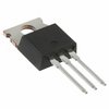
Part Details for STP9NK80Z by STMicroelectronics
Results Overview of STP9NK80Z by STMicroelectronics
- Distributor Offerings: (2 listings)
- Number of FFF Equivalents: (0 replacements)
- Tariff Estimator: (Not Available)
- Number of Functional Equivalents: (0 options)
- CAD Models: (Request Part)
- Part Data Attributes: (Available)
- Reference Designs: (Not Available)
Tip: Data for a part may vary between manufacturers. You can filter for manufacturers on the top of the page next to the part image and part number.
STP9NK80Z Information
STP9NK80Z by STMicroelectronics is a Power Field-Effect Transistor.
Power Field-Effect Transistors are under the broader part category of Transistors.
A transistor is a small semiconductor device used to amplify, control, or create electrical signals. When selecting a transistor, factors such as voltage, current rating, gain, and power dissipation must be considered, with common types. Read more about Transistors on our Transistors part category page.
Price & Stock for STP9NK80Z
| Part # | Distributor | Description | Stock | Price | Buy | |
|---|---|---|---|---|---|---|
|
DISTI #
497-5133-5-ND
|
DigiKey | MOSFET N-CH 800V 7.5A TO220AB Min Qty: 1000 Container: Tube |
0 Tube |
|
$1.1984 | Buy Now |
|
|
Vyrian | Power Field-Effect Transistor, 7.5A I(D), 800V, 1.2ohm, 1-Element, N-Channel, Silicon, Metal-oxide Semiconductor FET, TO-220AB | 12018 |
|
RFQ |
STP9NK80Z Part Data Attributes
|
|
STP9NK80Z
STMicroelectronics
Buy Now
Datasheet
|
Compare Parts:
STP9NK80Z
STMicroelectronics
Power Field-Effect Transistor, 7.5A I(D), 800V, 1.2ohm, 1-Element, N-Channel, Silicon, Metal-oxide Semiconductor FET, TO-220AB
|
| Rohs Code | Yes | |
| Part Life Cycle Code | Obsolete | |
| Part Package Code | TO-220AB | |
| Package Description | To-220, 3 Pin | |
| Pin Count | 3 | |
| ECCN Code | EAR99 | |
| Additional Feature | Avalanche Rated | |
| Avalanche Energy Rating (Eas) | 350 Mj | |
| Configuration | Single With Built-In Diode | |
| DS Breakdown Voltage-Min | 800 V | |
| Drain Current-Max (ID) | 7.5 A | |
| Drain-source On Resistance-Max | 1.2 Ω | |
| FET Technology | Metal-Oxide Semiconductor | |
| Feedback Cap-Max (Crss) | 10 Pf | |
| JEDEC-95 Code | TO-220AB | |
| JESD-30 Code | R-PSFM-T3 | |
| JESD-609 Code | e3 | |
| Number of Elements | 1 | |
| Number of Terminals | 3 | |
| Operating Mode | Enhancement Mode | |
| Operating Temperature-Max | 150 °C | |
| Package Body Material | Plastic/Epoxy | |
| Package Shape | Rectangular | |
| Package Style | Flange Mount | |
| Polarity/Channel Type | N-Channel | |
| Power Dissipation-Max (Abs) | 150 W | |
| Pulsed Drain Current-Max (IDM) | 30 A | |
| Qualification Status | Not Qualified | |
| Surface Mount | No | |
| Terminal Finish | Tin (Sn) | |
| Terminal Form | Through-Hole | |
| Terminal Position | Single | |
| Transistor Application | Switching | |
| Transistor Element Material | Silicon |
STP9NK80Z Frequently Asked Questions (FAQ)
-
The maximum junction temperature (Tj) of the STP9NK80Z is 150°C. However, it's recommended to keep the junction temperature below 125°C for reliable operation and to ensure a long lifespan.
-
To calculate the power dissipation of the STP9NK80Z, you need to consider the voltage drop across the device, the current flowing through it, and the thermal resistance. The power dissipation (Pd) can be calculated using the formula: Pd = (Vin - Vout) x Iout x Rth(j-a), where Vin is the input voltage, Vout is the output voltage, Iout is the output current, and Rth(j-a) is the thermal resistance from junction to ambient.
-
For good thermal performance, it's recommended to use a PCB layout that provides a large copper area for heat dissipation. The copper area should be connected to a solid ground plane to help dissipate heat. Additionally, it's recommended to place the device near a heat sink or a metal plate to further improve heat dissipation. The datasheet provides a recommended PCB layout and thermal management guidelines.
-
Yes, the STP9NK80Z is suitable for high-frequency switching applications up to 100 kHz. However, it's essential to consider the device's switching characteristics, such as the rise and fall times, and the gate drive requirements to ensure reliable operation. Additionally, the PCB layout and the choice of components should be optimized for high-frequency operation.
-
To protect the STP9NK80Z from overvoltage and overcurrent conditions, it's recommended to use a voltage regulator or a voltage clamp to limit the input voltage. Additionally, a current sense resistor and a fuse can be used to detect and limit the output current. It's also essential to follow the recommended operating conditions and to design the application with sufficient margins to ensure reliable operation.