-
Part Symbol
-
Footprint
-
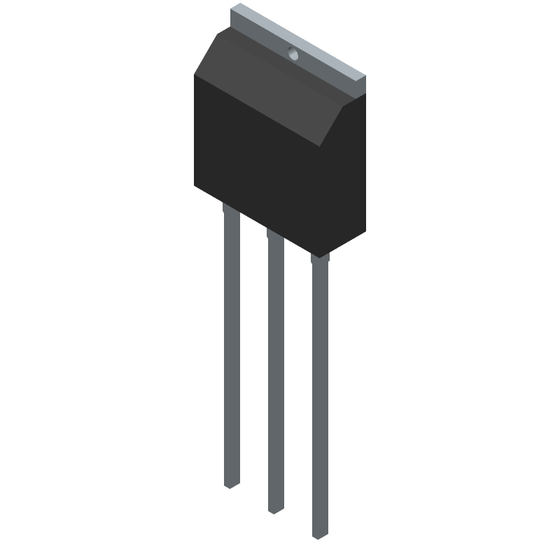
3D Model
Available Download Formats
By downloading CAD models, you agree to our Terms & Conditions and Privacy Policy
Power Field-Effect Transistor, 4.5A I(D), 600V, 1.2ohm, 1-Element, N-Channel, Silicon, Metal-oxide Semiconductor FET, TO-251
Tip: Data for a part may vary between manufacturers. You can filter for manufacturers on the top of the page next to the part image and part number.
STU6N60M2 by STMicroelectronics is a Power Field-Effect Transistor.
Power Field-Effect Transistors are under the broader part category of Transistors.
A transistor is a small semiconductor device used to amplify, control, or create electrical signals. When selecting a transistor, factors such as voltage, current rating, gain, and power dissipation must be considered, with common types. Read more about Transistors on our Transistors part category page.
| Part # | Distributor | Description | Stock | Price | Buy | |
|---|---|---|---|---|---|---|
|
DISTI #
STU6N60M2
|
Avnet Americas | - Rail/Tube (Alt: STU6N60M2) COO: China RoHS: Compliant Min Qty: 3000 Package Multiple: 3000 Container: Tube | 0 |
|
RFQ | |
|
|
STMicroelectronics | N-channel 600 V, 1.06 Ohm typ., 4.5 A MDmesh M2 Power MOSFET in IPAK package COO: China RoHS: Compliant Min Qty: 1 | 0 |
|
$0.7000 / $1.3600 | Buy Now |
|
|
Bristol Electronics | Trans MOSFET N-CH 600V 4.5A 3-Pin(3+Tab) IPAK Tube Min Qty: 1 | 2550 |
|
$0.3884 / $1.4940 | Buy Now |
|
|
Bristol Electronics | Trans MOSFET N-CH 600V 4.5A 3-Pin(3+Tab) IPAK Tube | 2117 |
|
RFQ | |
|
|
Quest Components | 2040 |
|
$0.4980 / $1.9920 | Buy Now | |
|
|
Quest Components | 2040 |
|
$0.7172 / $2.3905 | Buy Now | |
|
|
Vyrian | Power Field-Effect Transistor, 4.5A I(D), 600V, 1.2ohm, 1-Element, N-Channel, Silicon, Metal-oxide Semiconductor FET, TO-251 | 4051 |
|
RFQ |
By downloading CAD models, you agree to our Terms & Conditions and Privacy Policy
|
|
STU6N60M2
STMicroelectronics
Buy Now
Datasheet
|
Compare Parts:
STU6N60M2
STMicroelectronics
Power Field-Effect Transistor, 4.5A I(D), 600V, 1.2ohm, 1-Element, N-Channel, Silicon, Metal-oxide Semiconductor FET, TO-251
|
| Rohs Code | Yes | |
| Part Life Cycle Code | Obsolete | |
| Package Description | Ipak-3 | |
| ECCN Code | EAR99 | |
| Avalanche Energy Rating (Eas) | 86 Mj | |
| Case Connection | Drain | |
| Configuration | Single With Built-In Diode | |
| DS Breakdown Voltage-Min | 600 V | |
| Drain Current-Max (ID) | 4.5 A | |
| Drain-source On Resistance-Max | 1.2 Ω | |
| FET Technology | Metal-Oxide Semiconductor | |
| Feedback Cap-Max (Crss) | 0.7 Pf | |
| JEDEC-95 Code | TO-251 | |
| JESD-30 Code | R-PSIP-T3 | |
| JESD-609 Code | e3 | |
| Number of Elements | 1 | |
| Number of Terminals | 3 | |
| Operating Mode | Enhancement Mode | |
| Operating Temperature-Max | 150 °C | |
| Operating Temperature-Min | -55 °C | |
| Package Body Material | Plastic/Epoxy | |
| Package Shape | Rectangular | |
| Package Style | In-Line | |
| Peak Reflow Temperature (Cel) | Not Specified | |
| Polarity/Channel Type | N-Channel | |
| Power Dissipation-Max (Abs) | 60 W | |
| Pulsed Drain Current-Max (IDM) | 18 A | |
| Surface Mount | No | |
| Terminal Finish | Matte Tin (Sn) - Annealed | |
| Terminal Form | Through-Hole | |
| Terminal Position | Single | |
| Time@Peak Reflow Temperature-Max (s) | Not Specified | |
| Transistor Application | Switching | |
| Transistor Element Material | Silicon |
The maximum safe operating area (SOA) of the STU6N60M2 is not explicitly stated in the datasheet, but it can be estimated based on the device's thermal characteristics and voltage ratings. As a general rule, it's recommended to operate the device within the specified voltage and current ratings to ensure safe operation.
To ensure proper cooling, consider the device's thermal resistance (RthJA) and maximum junction temperature (Tj). Use a heat sink or thermal pad to reduce the thermal resistance, and ensure good airflow around the device. You can also use thermal simulation tools to estimate the device's temperature and optimize your design accordingly.
The recommended gate drive voltage for the STU6N60M2 is typically between 10V to 15V, depending on the specific application and switching frequency. A higher gate drive voltage can improve switching performance, but may also increase power consumption and EMI.
The internal diode of the STU6N60M2 can cause voltage spikes during switching. To mitigate this, use a snubber circuit or a diode clamp to limit the voltage spike. You can also use a gate driver with built-in diode emulation or a dedicated diode clamp IC.
The maximum allowed dv/dt for the STU6N60M2 is not explicitly stated in the datasheet, but it's typically recommended to limit dv/dt to 10V/ns or less to prevent voltage overshoot and ensure reliable operation.