| Part Number | Manufacturer | Composite Price | Description | Compare |
|---|---|---|---|---|
| TIP135 | Central Semiconductor Corp | Check for Price | Power Bipolar Transistor, 8A I(C), 60V V(BR)CEO, 1-Element, PNP, Silicon, TO-220AB, Plastic/Epoxy, 3 Pin | TIP135 vs TIP135 |
| TIP135 | Continental Device India Ltd | Check for Price | Power Bipolar Transistor, 8A I(C), 60V V(BR)CEO, 1-Element, PNP, Silicon, TO-220AB, Plastic/Epoxy, 3 Pin | TIP135 vs TIP135 |
| TIP135 | Baneasa SA | Check for Price | Power Bipolar Transistor, 8A I(C), 1-Element, PNP, Silicon, TO-220AB, Plastic/Epoxy, 3 Pin | TIP135 vs TIP135 |
| TIP135 | Crimson Semiconductor Inc | Check for Price | Power Bipolar Transistor, 8A I(C), 60V V(BR)CEO, 1-Element, PNP, Silicon, TO-220AB, Plastic/Epoxy, 3 Pin | TIP135 vs TIP135 |
Part Details for TIP135 by STMicroelectronics
Results Overview of TIP135 by STMicroelectronics
- Distributor Offerings: (4 listings)
- Number of FFF Equivalents: (4 replacements)
- Tariff Estimator: (Available) NEW
- Number of Functional Equivalents: (10 options)
- CAD Models: (Available)
- Part Data Attributes: (Available)
- Reference Designs: (Not Available)
Tip: Data for a part may vary between manufacturers. You can filter for manufacturers on the top of the page next to the part image and part number.
TIP135 Information
TIP135 by STMicroelectronics is a Power Bipolar Transistor.
Power Bipolar Transistors are under the broader part category of Transistors.
A transistor is a small semiconductor device used to amplify, control, or create electrical signals. When selecting a transistor, factors such as voltage, current rating, gain, and power dissipation must be considered, with common types. Read more about Transistors on our Transistors part category page.
Price & Stock for TIP135
| Part # | Distributor | Description | Stock | Price | Buy | |
|---|---|---|---|---|---|---|
|
|
Bristol Electronics | Trans Darlington PNP 60V 8A 2000mW 3-Pin(3+Tab) TO-220AB Tube | 9 |
|
RFQ | |
|
|
Quest Components | POWER BIPOLAR TRANSISTOR, 8A I(C), 60V V(BR)CEO, 1-ELEMENT, PNP, SILICON | 1856 |
|
$1.0350 / $2.7600 | Buy Now |
|
|
Quest Components | POWER BIPOLAR TRANSISTOR, 8A I(C), 60V V(BR)CEO, 1-ELEMENT, PNP, SILICON | 7 |
|
$2.9550 / $3.5460 | Buy Now |
|
|
ComSIT USA | COMPLEMENTARY SILICON POWER DARLINGTON TRANSISTOR Power Bipolar Transistor, 8A I(C), 60V V(BR)CEO, 1-Element, PNP, Silicon, TO-220AB, Plastic/Epoxy, 3 Pin ECCN: EAR99 RoHS: Compliant |
|
|
RFQ |
US Tariff Estimator: TIP135 by STMicroelectronics
Calculations from this tool are estimations only for imports into the United States. Please refer to the distributor or manufacturer and reference official US government sources and authorities to verify any final purchase costs.
TIP135 CAD Models
-
Part Symbol
-
Footprint
-
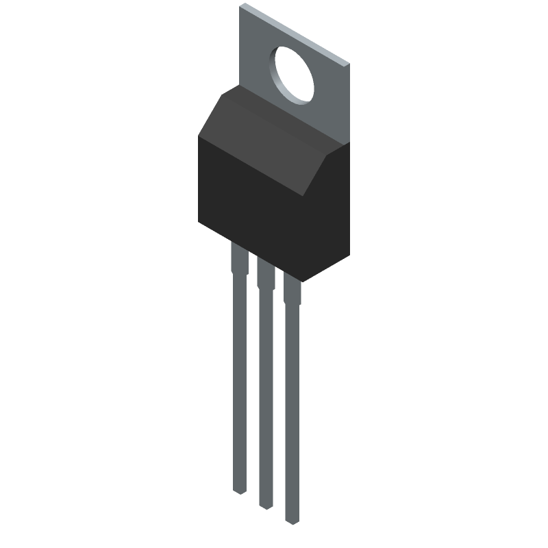
3D Model
Available Download Formats
By downloading CAD models, you agree to our Terms & Conditions and Privacy Policy
TIP135 Part Data Attributes
|
|
TIP135
STMicroelectronics
Buy Now
Datasheet
|
Compare Parts:
TIP135
STMicroelectronics
Power Bipolar Transistor, 8A I(C), 60V V(BR)CEO, 1-Element, PNP, Silicon, TO-220AB, Plastic/Epoxy, 3 Pin
|
| Rohs Code | Yes | |
| Part Life Cycle Code | Obsolete | |
| Part Package Code | TO-220AB | |
| Package Description | Plastic, To-220, 3 Pin | |
| Pin Count | 3 | |
| ECCN Code | EAR99 | |
| HTS Code | 8541.29.00.95 | |
| Collector Current-Max (IC) | 8 A | |
| Collector-Emitter Voltage-Max | 60 V | |
| Configuration | Darlington With Built-In Diode And Resistor | |
| DC Current Gain-Min (hFE) | 1000 | |
| JEDEC-95 Code | TO-220AB | |
| JESD-30 Code | R-PSFM-T3 | |
| JESD-609 Code | e3 | |
| Number of Elements | 1 | |
| Number of Terminals | 3 | |
| Operating Temperature-Max | 150 °C | |
| Package Body Material | Plastic/Epoxy | |
| Package Shape | Rectangular | |
| Package Style | Flange Mount | |
| Polarity/Channel Type | Pnp | |
| Power Dissipation Ambient-Max | 70 W | |
| Power Dissipation-Max (Abs) | 70 W | |
| Qualification Status | Not Qualified | |
| Surface Mount | No | |
| Terminal Finish | Matte Tin (Sn) | |
| Terminal Form | Through-Hole | |
| Terminal Position | Single | |
| Transistor Application | Switching | |
| Transistor Element Material | Silicon | |
| VCEsat-Max | 3 V |
Alternate Parts for TIP135
This table gives cross-reference parts and alternative options found for TIP135. The Form Fit Function (FFF) tab will give you the options that are more likely to serve as direct pin-to-pin alternates or drop-in parts. The Functional Equivalents tab will give you options that are likely to match the same function of TIP135, but it may not fit your design. Always verify details of parts you are evaluating, as these parts are offered as suggestions for what you are looking for and are not guaranteed.
TIP135 Frequently Asked Questions (FAQ)
-
The maximum safe operating area (SOA) for the TIP135 is not explicitly stated in the datasheet, but it can be estimated based on the device's thermal resistance and maximum junction temperature. As a general rule, it's recommended to keep the device within the SOA to prevent thermal runaway and ensure reliable operation.
-
To choose the correct heatsink for the TIP135, you need to consider the device's power dissipation, thermal resistance, and maximum junction temperature. A good starting point is to calculate the required thermal resistance of the heatsink based on the device's power dissipation and maximum junction temperature. You can then select a heatsink that meets or exceeds this requirement.
-
The recommended PCB layout for the TIP135 involves keeping the device's leads as short as possible, using a solid ground plane, and minimizing the thermal resistance between the device and the heatsink. It's also important to ensure good thermal conductivity between the device and the heatsink, and to avoid thermal hotspots.
-
To protect the TIP135 from electrical overstress (EOS), it's recommended to use a combination of voltage clamping devices, such as zener diodes or transient voltage suppressors (TVS), and to ensure that the device is operated within its recommended voltage and current ratings. Additionally, using a fuse or a current-limiting resistor can help prevent excessive current from flowing through the device.
-
The recommended storage and handling procedure for the TIP135 involves storing the devices in their original packaging, away from direct sunlight and moisture. It's also important to handle the devices by the body, rather than the leads, to prevent mechanical stress and damage. Additionally, it's recommended to use anti-static precautions when handling the devices to prevent electrostatic discharge (ESD) damage.