Tip: Data for a part may vary between manufacturers. You can filter for manufacturers on the top of the page next to the part image and part number.
ApplicationsConsumer Electronics
TLC59461PWP Information
TLC59461PWP by Texas Instruments is a Display Driver.
Display Drivers are under the broader part category of Drivers And Interfaces.
A driver controls the current or voltage delivered to components like LCDs or motors, while an interface component connects systems for data transfer and control. Read more about Drivers And Interfaces on our Drivers And Interfaces part category page.
US Tariff Estimator: TLC59461PWP by Texas Instruments
Calculations from this tool are estimations only for imports into the United States. Please refer to the distributor or manufacturer and reference official US government sources and authorities to verify any final purchase costs.
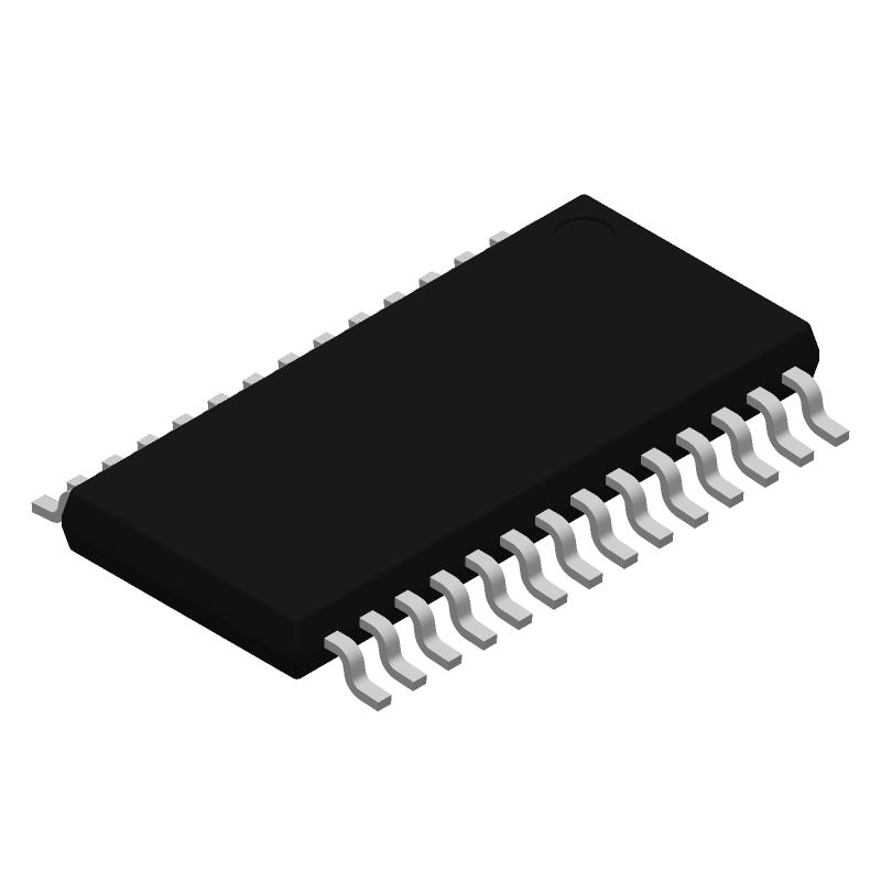
Small Outline, Heat Sink/Slug, Thin Profile, Shrink Pitch
Packing Method
Tube
Peak Reflow Temperature (Cel)
260
Qualification Status
Not Qualified
Seated Height-Max
1.2 Mm
Supply Current-Max
45 Ma
Supply Voltage-Max
5.5 V
Supply Voltage-Min
3 V
Supply Voltage-Nom
3.3 V
Surface Mount
Yes
Temperature Grade
Industrial
Terminal Finish
Nickel/Palladium/Gold (Ni/Pd/Au)
Terminal Form
Gull Wing
Terminal Pitch
0.65 Mm
Terminal Position
Dual
Time@Peak Reflow Temperature-Max (s)
30
Width
4.4 Mm
fmax-Min
30 Mhz
Alternate Parts for TLC59461PWP
This table gives cross-reference parts and alternative options found for TLC59461PWP. The Form Fit Function (FFF) tab will give you the options that are more likely to serve as direct pin-to-pin alternates or drop-in parts. The Functional Equivalents tab will give you options that are likely to match the same function of TLC59461PWP, but it may not fit your design. Always verify details of parts you are evaluating, as these parts are offered as suggestions for what you are looking for and are not guaranteed.
The maximum frequency of the clock input is 30 MHz, but it's recommended to keep it below 20 MHz for reliable operation.
The recommended sequence is: GSCLK low, SCLK low, XLAT high, then GSCLK high, SCLK high, and finally XLAT low. This ensures proper data loading and latch operation.
The VPRG pin is used to set the internal voltage reference for the grayscale PWM generator. Connect it to a voltage source between 1.2V and 3.3V to set the reference voltage, or leave it open for a default internal reference of 1.2V.
The TLC59461PWP has a built-in thermal shutdown feature that disables the device when it overheats. To handle this, monitor the TSD pin, which goes low when the device is in thermal shutdown. When this occurs, stop sending data and wait for the device to cool down before resuming operation.
Keep the GSCLK, SCLK, and XLAT signals short and away from noisy signals. Use a solid ground plane and decouple the power supply with a 0.1uF capacitor. Also, keep the OUTx pins away from the power supply and ground pins to minimize noise coupling.