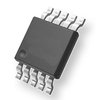
| Part Number | Manufacturer | Composite Price | Description | Compare |
|---|---|---|---|---|
| VNV35N07-E | STMicroelectronics | Check for Price | Power Field-Effect Transistor, 60V, 0.035ohm, 1-Element, N-Channel, Silicon, Metal-oxide Semiconductor FET | VNV35N07 vs VNV35N07-E |
| VNV35N07TR-E | STMicroelectronics | Check for Price | Power Field-Effect Transistor, 60V, 0.035ohm, 1-Element, N-Channel, Silicon, Metal-oxide Semiconductor FET | VNV35N07 vs VNV35N07TR-E |
Part Details for VNV35N07 by STMicroelectronics
Results Overview of VNV35N07 by STMicroelectronics
- Distributor Offerings: (2 listings)
- Number of FFF Equivalents: (2 replacements)
- Tariff Estimator: (Not Available)
- Number of Functional Equivalents: (5 options)
- CAD Models: (Request Part)
- Part Data Attributes: (Available)
- Reference Designs: (Not Available)
Tip: Data for a part may vary between manufacturers. You can filter for manufacturers on the top of the page next to the part image and part number.
VNV35N07 Information
VNV35N07 by STMicroelectronics is a Power Field-Effect Transistor.
Power Field-Effect Transistors are under the broader part category of Transistors.
A transistor is a small semiconductor device used to amplify, control, or create electrical signals. When selecting a transistor, factors such as voltage, current rating, gain, and power dissipation must be considered, with common types. Read more about Transistors on our Transistors part category page.
Price & Stock for VNV35N07
| Part # | Distributor | Description | Stock | Price | Buy | |
|---|---|---|---|---|---|---|
|
DISTI #
497-3319-5-ND
|
DigiKey | IC PWR DRIVER N-CHAN 1:1 PWRSO10 Container: Tube |
0 Tube |
|
Buy Now | |
|
DISTI #
VNV35N07
|
Avnet Americas | - Rail/Tube (Alt: VNV35N07) COO: Morocco RoHS: Compliant Min Qty: 1000 Package Multiple: 1000 Lead time: 29 Weeks, 2 Days Container: Tube | 0 |
|
RFQ |
VNV35N07 Part Data Attributes
|
|
VNV35N07
STMicroelectronics
Buy Now
Datasheet
|
Compare Parts:
VNV35N07
STMicroelectronics
Power Field-Effect Transistor, 60V, 0.035ohm, 1-Element, N-Channel, Silicon, Metal-oxide Semiconductor FET
|
| Pbfree Code | Yes | |
| Rohs Code | Yes | |
| Part Life Cycle Code | Obsolete | |
| Part Package Code | SOIC | |
| Package Description | Sop-10 | |
| Pin Count | 10 | |
| ECCN Code | EAR99 | |
| Avalanche Energy Rating (Eas) | 100 Mj | |
| Configuration | Complex | |
| DS Breakdown Voltage-Min | 60 V | |
| Drain Current-Max (ID) | 0.5 A | |
| Drain-source On Resistance-Max | 0.035 Ω | |
| FET Technology | Metal-Oxide Semiconductor | |
| Feedback Cap-Max (Crss) | 10 Pf | |
| JESD-30 Code | R-PDSO-G10 | |
| Moisture Sensitivity Level | 3 | |
| Number of Elements | 1 | |
| Number of Terminals | 10 | |
| Operating Mode | Enhancement Mode | |
| Operating Temperature-Max | 150 °C | |
| Package Body Material | Plastic/Epoxy | |
| Package Shape | Rectangular | |
| Package Style | Small Outline | |
| Peak Reflow Temperature (Cel) | 250 | |
| Polarity/Channel Type | N-Channel | |
| Power Dissipation-Max (Abs) | 125 W | |
| Pulsed Drain Current-Max (IDM) | 1.3 A | |
| Surface Mount | Yes | |
| Terminal Finish | Matte Tin (Sn) - Annealed | |
| Terminal Form | Gull Wing | |
| Terminal Position | Dual | |
| Time@Peak Reflow Temperature-Max (s) | 30 | |
| Transistor Application | Switching | |
| Transistor Element Material | Silicon | |
| Turn-off Time-Max (toff) | 1350 Ns | |
| Turn-on Time-Max (ton) | 800 Ns |
Alternate Parts for VNV35N07
This table gives cross-reference parts and alternative options found for VNV35N07. The Form Fit Function (FFF) tab will give you the options that are more likely to serve as direct pin-to-pin alternates or drop-in parts. The Functional Equivalents tab will give you options that are likely to match the same function of VNV35N07, but it may not fit your design. Always verify details of parts you are evaluating, as these parts are offered as suggestions for what you are looking for and are not guaranteed.
VNV35N07 Frequently Asked Questions (FAQ)
-
The maximum junction temperature (Tj) of the VNV35N07 is 150°C, as specified in the datasheet. However, it's recommended to keep the junction temperature below 125°C for reliable operation and to prevent thermal runaway.
-
To ensure proper biasing, make sure to follow the recommended operating conditions in the datasheet. This includes providing a stable input voltage (VIN) within the specified range (typically 5.5V to 36V), and ensuring the output voltage (VOUT) is within the specified range (typically 5V to 24V). Additionally, ensure the input and output capacitors are properly sized and placed close to the device.
-
For optimal PCB layout, follow these guidelines: keep the input and output capacitors close to the device, use a solid ground plane, and keep the high-current paths short and wide. Avoid routing high-frequency signals near the device, and use a shielded layout to minimize EMI. Additionally, ensure good thermal dissipation by providing a thermal pad or heat sink, and keeping the device away from other heat sources.
-
To protect the VNV35N07 from overvoltage and undervoltage conditions, consider adding external protection circuits such as overvoltage protection (OVP) and undervoltage lockout (UVLO) circuits. These can be implemented using external components such as zener diodes, resistors, and comparators. Additionally, ensure the input voltage is within the specified range and use a voltage regulator or voltage supervisor to monitor the input voltage.
-
The recommended input capacitor value and type for the VNV35N07 depends on the specific application and operating conditions. However, as a general guideline, use a low-ESR ceramic capacitor with a value between 1uF to 10uF, and a voltage rating that exceeds the maximum input voltage. X5R or X7R dielectric capacitors are suitable for most applications.