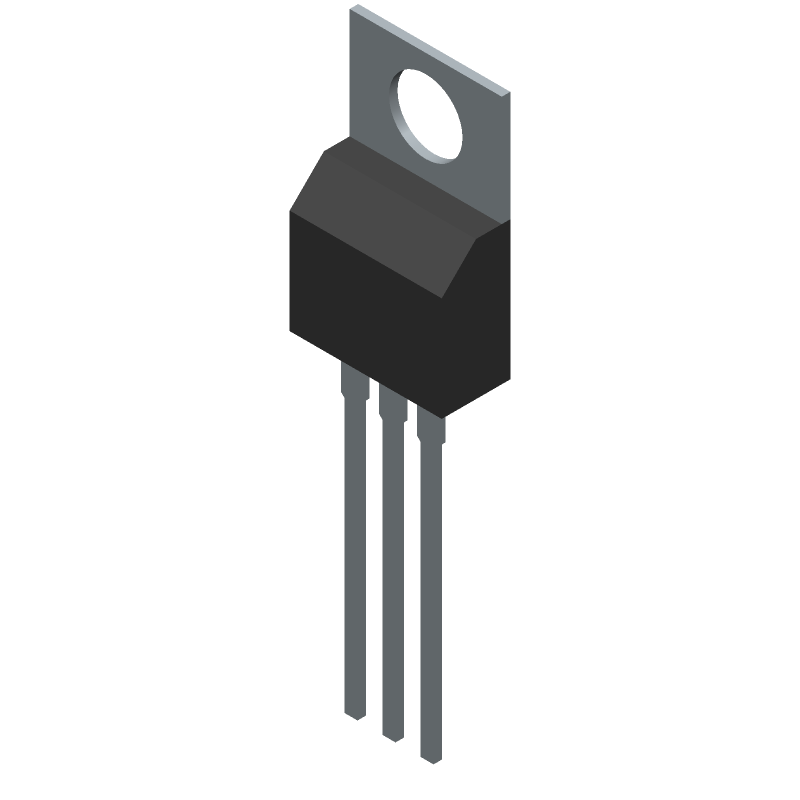
| Part Number | Manufacturer | Composite Price | Description | Compare |
|---|---|---|---|---|
| STF18N60M2 | STMicroelectronics | $0.9600 | Power Field-Effect Transistor, 13A I(D), 600V, 0.28ohm, 1-Element, N-Channel, Silicon, Metal-oxide Semiconductor FET, TO-220AB | STF10N60M2 vs STF18N60M2 |
| STF10N62K3 | STMicroelectronics | $1.1394 | Power Field-Effect Transistor, 8.4A I(D), 620V, 0.75ohm, 1-Element, N-Channel, Silicon, Metal-oxide Semiconductor FET, TO-220AB | STF10N60M2 vs STF10N62K3 |
| STF6N95K5 | STMicroelectronics | $1.5183 | Power Field-Effect Transistor, 9A I(D), 950V, 1.25ohm, 1-Element, N-Channel, Silicon, Metal-oxide Semiconductor FET, TO-220AB | STF10N60M2 vs STF6N95K5 |
| STF7NM60N | STMicroelectronics | $1.5442 | Power Field-Effect Transistor, 5A I(D), 600V, 0.9ohm, 1-Element, N-Channel, Silicon, Metal-oxide Semiconductor FET, TO-220AB | STF10N60M2 vs STF7NM60N |
| STF19NM50N | STMicroelectronics | $2.1232 | Power Field-Effect Transistor, 14A I(D), 500V, 0.25ohm, 1-Element, N-Channel, Silicon, Metal-oxide Semiconductor FET, TO-220AB | STF10N60M2 vs STF19NM50N |
| STF5N52K3 | STMicroelectronics | Check for Price | Power Field-Effect Transistor, 4.4A I(D), 525V, 1.5ohm, 1-Element, N-Channel, Silicon, Metal-oxide Semiconductor FET, TO-220AB | STF10N60M2 vs STF5N52K3 |
| STF5N52U | STMicroelectronics | Check for Price | Power Field-Effect Transistor, 4.4A I(D), 525V, 1.5ohm, 1-Element, N-Channel, Silicon, Metal-oxide Semiconductor FET, TO-220AB | STF10N60M2 vs STF5N52U |
| STF12NK60Z | STMicroelectronics | Check for Price | Power Field-Effect Transistor | STF10N60M2 vs STF12NK60Z |
| STF10NM50N | STMicroelectronics | Check for Price | Power Field-Effect Transistor, 7A I(D), 500V, 0.63ohm, 1-Element, N-Channel, Silicon, Metal-oxide Semiconductor FET, TO-220AB | STF10N60M2 vs STF10NM50N |
| STF11NM60N | STMicroelectronics | Check for Price | Power Field-Effect Transistor, 10A I(D), 600V, 0.45ohm, 1-Element, N-Channel, Silicon, Metal-oxide Semiconductor FET, TO-220AB | STF10N60M2 vs STF11NM60N |
Part Details for STF10N60M2 by STMicroelectronics
Results Overview of STF10N60M2 by STMicroelectronics
- Distributor Offerings: (13 listings)
- Number of FFF Equivalents: (0 replacements)
- Tariff Estimator: (Not Available)
- Number of Functional Equivalents: (10 options)
- CAD Models: (Available)
- Part Data Attributes: (Available)
- Reference Designs: (Not Available)
Tip: Data for a part may vary between manufacturers. You can filter for manufacturers on the top of the page next to the part image and part number.
Applications
Consumer Electronics
Energy and Power Systems
Renewable Energy
STF10N60M2 Information
STF10N60M2 by STMicroelectronics is a Power Field-Effect Transistor.
Power Field-Effect Transistors are under the broader part category of Transistors.
A transistor is a small semiconductor device used to amplify, control, or create electrical signals. When selecting a transistor, factors such as voltage, current rating, gain, and power dissipation must be considered, with common types. Read more about Transistors on our Transistors part category page.
Price & Stock for STF10N60M2
| Part # | Distributor | Description | Stock | Price | Buy | |
|---|---|---|---|---|---|---|
|
DISTI #
45AC7550
|
Newark | Mosfet, N-Ch, 600V, 7.5A, To-220Fp, |Stmicroelectronics STF10N60M2 RoHS: Compliant Min Qty: 1 Package Multiple: 1 Date Code: 0 Container: Bulk | 107 |
|
$0.8670 / $2.3500 | Buy Now |
|
DISTI #
497-13945-5-ND
|
DigiKey | MOSFET N-CH 600V 7.5A TO220FP Min Qty: 1 Container: Tube |
457 Tube |
|
$0.7147 / $2.0900 | Buy Now |
|
DISTI #
93258226
|
Verical | Trans MOSFET N-CH 600V 7.5A 3-Pin(3+Tab) TO-220FP Tube RoHS: Exempt Min Qty: 3 Package Multiple: 1 | Americas - 2835 |
|
$1.6070 | Buy Now |
|
DISTI #
511-STF10N60M2
|
Mouser Electronics | MOSFETs N-CH 600V 0.56Ohm 7.5A MDmesh M2 RoHS: Compliant | 2194 |
|
$0.5900 / $2.0900 | Buy Now |
|
DISTI #
P02:6590_05231660
|
Arrow Electronics | Trans MOSFET N-CH 600V 7.5A 3-Pin(3+Tab) TO-220FP Tube RoHS: Exempt Min Qty: 1 Package Multiple: 1 Lead time: 24 Weeks | Asia - 2835 |
|
$1.6070 | Buy Now |
|
|
Future Electronics | N-Channel 600 V 600 mOhm Flange Mount MDmesh II Plus Power Mosfet -TO-220FP RoHS: Compliant pbFree: Yes Min Qty: 2000 Package Multiple: 1000 Lead time: 24 Weeks Container: Tube | 0Tube |
|
$0.9050 / $0.9500 | Buy Now |
|
|
Future Electronics | N-Channel 600 V 600 mOhm Flange Mount MDmesh II Plus Power Mosfet -TO-220FP RoHS: Compliant pbFree: Yes Min Qty: 2000 Package Multiple: 1000 Lead time: 24 Weeks Container: Tube | 0Tube |
|
$0.9050 / $0.9500 | Buy Now |
|
|
Bristol Electronics | Trans MOSFET N-CH 600V 7.5A 3-Pin(3+Tab) TO-220FP Tube | 1900 |
|
RFQ | |
|
DISTI #
P02:6590_05231660
|
Arrow Electronics | Trans MOSFET N-CH 600V 7.5A 3-Pin(3+Tab) TO-220FP Tube RoHS: Exempt Min Qty: 1 Package Multiple: 1 Lead time: 24 Weeks | Asia - 2835 |
|
$1.6070 | Buy Now |
|
DISTI #
93258226
|
Verical | Trans MOSFET N-CH 600V 7.5A 3-Pin(3+Tab) TO-220FP Tube RoHS: Exempt Min Qty: 3 Package Multiple: 1 | Americas - 2835 |
|
$1.6070 | Buy Now |
STF10N60M2 CAD Models
-
Part Symbol
-
Footprint
-
3D Model
Available Download Formats
By downloading CAD models, you agree to our Terms & Conditions and Privacy Policy
STF10N60M2 Part Data Attributes
|
|
STF10N60M2
STMicroelectronics
Buy Now
Datasheet
|
Compare Parts:
STF10N60M2
STMicroelectronics
Power Field-Effect Transistor, 7.5A I(D), 600V, 0.6ohm, 1-Element, N-Channel, Silicon, Metal-oxide Semiconductor FET, TO-220AB
|
| Rohs Code | Yes | |
| Part Life Cycle Code | Active | |
| Package Description | To-220fp, 3 Pin | |
| ECCN Code | EAR99 | |
| Factory Lead Time | 14 Weeks | |
| Avalanche Energy Rating (Eas) | 110 Mj | |
| Case Connection | Isolated | |
| Configuration | Single With Built-In Diode | |
| DS Breakdown Voltage-Min | 600 V | |
| Drain Current-Max (ID) | 7.5 A | |
| Drain-source On Resistance-Max | 0.6 Ω | |
| FET Technology | Metal-Oxide Semiconductor | |
| Feedback Cap-Max (Crss) | 0.84 Pf | |
| JEDEC-95 Code | TO-220AB | |
| JESD-30 Code | R-PSFM-T3 | |
| Number of Elements | 1 | |
| Number of Terminals | 3 | |
| Operating Mode | Enhancement Mode | |
| Operating Temperature-Max | 150 °C | |
| Operating Temperature-Min | -55 °C | |
| Package Body Material | Plastic/Epoxy | |
| Package Shape | Rectangular | |
| Package Style | Flange Mount | |
| Peak Reflow Temperature (Cel) | Not Specified | |
| Polarity/Channel Type | N-Channel | |
| Power Dissipation-Max (Abs) | 25 W | |
| Pulsed Drain Current-Max (IDM) | 30 A | |
| Surface Mount | No | |
| Terminal Form | Through-Hole | |
| Terminal Position | Single | |
| Time@Peak Reflow Temperature-Max (s) | Not Specified | |
| Transistor Application | Switching | |
| Transistor Element Material | Silicon |
Alternate Parts for STF10N60M2
This table gives cross-reference parts and alternative options found for STF10N60M2. The Form Fit Function (FFF) tab will give you the options that are more likely to serve as direct pin-to-pin alternates or drop-in parts. The Functional Equivalents tab will give you options that are likely to match the same function of STF10N60M2, but it may not fit your design. Always verify details of parts you are evaluating, as these parts are offered as suggestions for what you are looking for and are not guaranteed.
STF10N60M2 Frequently Asked Questions (FAQ)
-
The maximum safe operating area (SOA) for the STF10N60M2 is not explicitly stated in the datasheet. However, it can be estimated based on the device's thermal resistance, maximum junction temperature, and power dissipation. A safe operating area can be estimated to be around 10-15A for 10ms pulses, but this should be verified through simulation and testing.
-
To minimize switching losses, ensure that the gate drive voltage is sufficient (typically 10-15V) and the gate resistance is low (typically <10 ohms). Also, ensure that the gate drive signal has a fast rise and fall time (<10ns) and is properly synchronized with the switching frequency.
-
To minimize parasitic inductance and capacitance, use a compact PCB layout with short, wide traces for the drain, source, and gate connections. Use a ground plane to reduce inductance and capacitance. Keep the gate drive circuitry close to the MOSFET to minimize stray inductance. Use a Kelvin connection for the gate drive to reduce parasitic inductance.
-
For high-power applications, ensure good thermal contact between the MOSFET and the heat sink. Use a heat sink with a high thermal conductivity (e.g., copper or aluminum) and apply a thermal interface material (e.g., thermal paste or thermal tape). Ensure good airflow around the heat sink to dissipate heat efficiently.
-
For high-reliability applications, consider adding protection circuits such as overvoltage protection (OVP), undervoltage protection (UVP), and overcurrent protection (OCP). Use a voltage regulator to regulate the gate drive voltage and ensure that the MOSFET is not exposed to excessive voltage or current.