
| Part Number | Manufacturer | Composite Price | Description | Compare |
|---|---|---|---|---|
| 2SD1723 | SANYO Electric Co Ltd | Check for Price | Power Bipolar Transistor, 8A I(C), 50V V(BR)CEO, 1-Element, NPN, Silicon, Plastic/Epoxy, 3 Pin | STN851 vs 2SD1723 |
| 2SD1668 | SANYO Electric Co Ltd | Check for Price | Power Bipolar Transistor, 7A I(C), 50V V(BR)CEO, 1-Element, NPN, Silicon, TO-220AB, Plastic/Epoxy, 3 Pin | STN851 vs 2SD1668 |
| 2SD1723 | SANYO Semiconductor Co Ltd | Check for Price | Power Bipolar Transistor, 8A I(C), 50V V(BR)CEO, 1-Element, NPN, Silicon, Plastic/Epoxy, 3 Pin | STN851 vs 2SD1723 |
| 2SC5076 | Toshiba America Electronic Components | Check for Price | Power Bipolar Transistor, 5A I(C), 50V V(BR)CEO, 1-Element, NPN, Silicon, Plastic/Epoxy, 3 Pin | STN851 vs 2SC5076 |
| 2SD1722 | SANYO Semiconductor Co Ltd | Check for Price | Power Bipolar Transistor, 5A I(C), 50V V(BR)CEO, 1-Element, NPN, Silicon, Plastic/Epoxy, 3 Pin | STN851 vs 2SD1722 |
| 2SC4728 | SANYO Electric Co Ltd | Check for Price | Power Bipolar Transistor, 5A I(C), 50V V(BR)CEO, 1-Element, NPN, Silicon, Plastic/Epoxy, 3 Pin | STN851 vs 2SC4728 |
| ZTX851 | Zetex / Diodes Inc | Check for Price | Power Bipolar Transistor, 5A I(C), 60V V(BR)CEO, 1-Element, NPN, Silicon, Plastic/Epoxy, 3 Pin | STN851 vs ZTX851 |
| 2SC5610 | SANYO Semiconductor Co Ltd | Check for Price | Power Bipolar Transistor, 7A I(C), 60V V(BR)CEO, 1-Element, NPN, Silicon, Plastic/Epoxy, 3 Pin | STN851 vs 2SC5610 |
| ZTX851STOB | Zetex / Diodes Inc | Check for Price | Power Bipolar Transistor, 5A I(C), 60V V(BR)CEO, 1-Element, NPN, Silicon, Plastic/Epoxy, 3 Pin | STN851 vs ZTX851STOB |
| ZTX851STZ | Zetex / Diodes Inc | Check for Price | Power Bipolar Transistor, 5A I(C), 60V V(BR)CEO, 1-Element, NPN, Silicon, Plastic/Epoxy, 3 Pin | STN851 vs ZTX851STZ |
Part Details for STN851 by STMicroelectronics
Results Overview of STN851 by STMicroelectronics
- Distributor Offerings: (2 listings)
- Number of FFF Equivalents: (0 replacements)
- Tariff Estimator: (Not Available)
- Number of Functional Equivalents: (10 options)
- CAD Models: (Available)
- Part Data Attributes: (Available)
- Reference Designs: (Not Available)
Tip: Data for a part may vary between manufacturers. You can filter for manufacturers on the top of the page next to the part image and part number.
STN851 Information
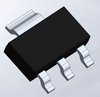
STN851 by STMicroelectronics is a Power Bipolar Transistor.
Power Bipolar Transistors are under the broader part category of Transistors.
A transistor is a small semiconductor device used to amplify, control, or create electrical signals. When selecting a transistor, factors such as voltage, current rating, gain, and power dissipation must be considered, with common types. Read more about Transistors on our Transistors part category page.
Price & Stock for STN851
| Part # | Distributor | Description | Stock | Price | Buy | |
|---|---|---|---|---|---|---|
|
DISTI #
93140402
|
Verical | Trans GP BJT NPN 60V 5A 1600mW 4-Pin(3+Tab) SOT-223 T/R RoHS: Exempt Min Qty: 3000 Package Multiple: 1000 Date Code: 2445 | Americas - 6000 |
|
$0.2919 | Buy Now |
|
DISTI #
88156399
|
Verical | Trans GP BJT NPN 60V 5A 1600mW 4-Pin(3+Tab) SOT-223 T/R RoHS: Exempt Min Qty: 1000 Package Multiple: 1000 Date Code: 2514 | Americas - 4000 |
|
$0.2223 / $0.2320 | Buy Now |
STN851 CAD Models
-
Part Symbol
-
Footprint
-
3D Model
Available Download Formats
By downloading CAD models, you agree to our Terms & Conditions and Privacy Policy
STN851 Part Data Attributes
|
|
STN851
STMicroelectronics
Buy Now
Datasheet
|
Compare Parts:
STN851
STMicroelectronics
Power Bipolar Transistor, 5A I(C), 60V V(BR)CEO, 1-Element, NPN, Silicon, Plastic/Epoxy, 4 Pin
|
| Rohs Code | Yes | |
| Part Life Cycle Code | Active | |
| Part Package Code | SOT-223 | |
| Package Description | Sot-223, 4 Pin | |
| Pin Count | 4 | |
| ECCN Code | EAR99 | |
| Factory Lead Time | 14 Weeks | |
| Case Connection | Collector | |
| Collector Current-Max (IC) | 5 A | |
| Collector-Emitter Voltage-Max | 60 V | |
| Configuration | Single | |
| DC Current Gain-Min (hFE) | 30 | |
| JESD-30 Code | R-PDSO-G4 | |
| JESD-609 Code | e3 | |
| Moisture Sensitivity Level | 1 | |
| Number of Elements | 1 | |
| Number of Terminals | 4 | |
| Operating Temperature-Max | 150 °C | |
| Package Body Material | Plastic/Epoxy | |
| Package Shape | Rectangular | |
| Package Style | Small Outline | |
| Packing Method | Tr | |
| Peak Reflow Temperature (Cel) | 260 | |
| Polarity/Channel Type | Npn | |
| Power Dissipation-Max (Abs) | 1.6 W | |
| Qualification Status | Not Qualified | |
| Surface Mount | Yes | |
| Terminal Finish | Matte Tin (Sn) - Annealed | |
| Terminal Form | Gull Wing | |
| Terminal Position | Dual | |
| Time@Peak Reflow Temperature-Max (s) | 30 | |
| Transistor Application | Switching | |
| Transistor Element Material | Silicon | |
| Transition Frequency-Nom (fT) | 130 Mhz |
Alternate Parts for STN851
This table gives cross-reference parts and alternative options found for STN851. The Form Fit Function (FFF) tab will give you the options that are more likely to serve as direct pin-to-pin alternates or drop-in parts. The Functional Equivalents tab will give you options that are likely to match the same function of STN851, but it may not fit your design. Always verify details of parts you are evaluating, as these parts are offered as suggestions for what you are looking for and are not guaranteed.
STN851 Frequently Asked Questions (FAQ)
-
The recommended operating temperature range for the STN851 is -40°C to 125°C.
-
To properly handle POR and BOR, ensure that the power supply voltage (VDD) is stable and within the recommended range. Also, add a capacitor (e.g., 10nF) between VDD and GND to filter out noise and ensure a clean power-on reset.
-
The STN851 supports a maximum clock frequency of 32 MHz.
-
To configure the UART, set the baud rate, data bits, parity, and stop bits according to your application's requirements. Ensure that the UART clock is properly configured and that the transmitter and receiver are enabled.
-
The ADC converts analog signals to digital values. To use the ADC, configure the ADC clock, select the desired channel, and enable the ADC. Then, start the conversion and read the resulting digital value.