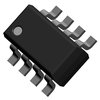
Part Details for AP4800AGM by Advanced Power Electronics Corp
Results Overview of AP4800AGM by Advanced Power Electronics Corp
- Distributor Offerings: (1 listing)
- Number of FFF Equivalents: (0 replacements)
- Tariff Estimator: (Not Available)
- Number of Functional Equivalents: (0 options)
- CAD Models: (Request Part)
- Part Data Attributes: (Available)
- Reference Designs: (Not Available)
Tip: Data for a part may vary between manufacturers. You can filter for manufacturers on the top of the page next to the part image and part number.
AP4800AGM Information
AP4800AGM by Advanced Power Electronics Corp is a Power Field-Effect Transistor.
Power Field-Effect Transistors are under the broader part category of Transistors.
A transistor is a small semiconductor device used to amplify, control, or create electrical signals. When selecting a transistor, factors such as voltage, current rating, gain, and power dissipation must be considered, with common types. Read more about Transistors on our Transistors part category page.
Price & Stock for AP4800AGM
| Part # | Distributor | Description | Stock | Price | Buy | |
|---|---|---|---|---|---|---|
|
|
Bristol Electronics | 3000 |
|
RFQ |
AP4800AGM Part Data Attributes
|
|
AP4800AGM
Advanced Power Electronics Corp
Buy Now
Datasheet
|
Compare Parts:
AP4800AGM
Advanced Power Electronics Corp
Power Field-Effect Transistor, 30V, 0.018ohm, 1-Element, N-Channel, Silicon, Metal-oxide Semiconductor FET
|
| Part Life Cycle Code | Obsolete | |
| Part Package Code | SOT | |
| Package Description | Rohs Compliant, Sop-8 | |
| Pin Count | 8 | |
| ECCN Code | EAR99 | |
| Configuration | Single With Built-In Diode | |
| DS Breakdown Voltage-Min | 30 V | |
| Drain-source On Resistance-Max | 0.018 Ω | |
| FET Technology | Metal-Oxide Semiconductor | |
| JESD-30 Code | R-PDSO-G8 | |
| Number of Elements | 1 | |
| Number of Terminals | 8 | |
| Operating Mode | Enhancement Mode | |
| Operating Temperature-Max | 150 °C | |
| Package Body Material | Plastic/Epoxy | |
| Package Shape | Rectangular | |
| Package Style | Small Outline | |
| Polarity/Channel Type | N-Channel | |
| Pulsed Drain Current-Max (IDM) | 40 A | |
| Qualification Status | Not Qualified | |
| Surface Mount | Yes | |
| Terminal Form | Gull Wing | |
| Terminal Position | Dual | |
| Transistor Application | Switching | |
| Transistor Element Material | Silicon |
AP4800AGM Frequently Asked Questions (FAQ)
-
The recommended PCB layout for optimal thermal performance involves placing the AP4800AGM near a thermal pad or heat sink, ensuring good thermal conductivity between the device and the PCB, and keeping the PCB traces as short and wide as possible to minimize thermal resistance.
-
To ensure reliable operation in high-temperature environments, it is recommended to derate the device's power dissipation according to the temperature derating curve provided in the datasheet, and to ensure good airflow around the device to prevent thermal buildup.
-
The recommended input and output capacitors for the AP4800AGM are low-ESR ceramic capacitors with a voltage rating of at least 25V and a capacitance value of 10uF to 22uF. The specific capacitor values and types may vary depending on the application and operating conditions.
-
To protect the AP4800AGM from overvoltage and undervoltage conditions, it is recommended to use a voltage supervisor or a voltage monitor IC to detect and respond to voltage faults, and to add overvoltage protection (OVP) and undervoltage protection (UVP) circuits as needed.
-
The recommended startup sequence for the AP4800AGM involves applying the input voltage first, followed by the enable signal, and then the output voltage. This sequence helps to prevent unwanted startup behavior and ensures reliable operation.