Part Details for CSD18532KCS by Texas Instruments
Results Overview of CSD18532KCS by Texas Instruments
- Distributor Offerings: (4 listings)
- Number of FFF Equivalents: (0 replacements)
- Tariff Estimator: (Available) NEW
- Number of Functional Equivalents: (0 options)
- CAD Models: (Available)
- Part Data Attributes: (Available)
- Reference Designs: (Available)
Tip: Data for a part may vary between manufacturers. You can filter for manufacturers on the top of the page next to the part image and part number.
CSD18532KCS Information
CSD18532KCS by Texas Instruments is a Power Field-Effect Transistor.
Power Field-Effect Transistors are under the broader part category of Transistors.
A transistor is a small semiconductor device used to amplify, control, or create electrical signals. When selecting a transistor, factors such as voltage, current rating, gain, and power dissipation must be considered, with common types. Read more about Transistors on our Transistors part category page.
Price & Stock for CSD18532KCS
| Part # | Distributor | Description | Stock | Price | Buy | |
|---|---|---|---|---|---|---|
|
DISTI #
296-34941-5-ND
|
DigiKey | MOSFET N-CH 60V 100A TO220-3 Min Qty: 1 Container: Tube |
1216 Tube |
|
$1.1197 / $3.1000 | Buy Now |
|
DISTI #
595-CSD18532KCS
|
Mouser Electronics | MOSFETs 60-V N-Chanel NxFT P wr MOSFETs RoHS: Compliant | 1304 |
|
$1.0100 / $3.1000 | Buy Now |
|
|
Quest Components | 100A, 60V, 0.0053OHM, N-CHANNEL, SI, POWER, MOSFET, TO-220 | 6 |
|
$1.5957 / $1.7345 | Buy Now |
|
DISTI #
CSD18532KCS
|
TME | Transistor: N-MOSFET, unipolar, 60V, 100A, 250W, TO220-3 Min Qty: 1 | 209 |
|
$1.3300 / $2.4600 | Buy Now |
US Tariff Estimator: CSD18532KCS by Texas Instruments
Calculations from this tool are estimations only for imports into the United States. Please refer to the distributor or manufacturer and reference official US government sources and authorities to verify any final purchase costs.
CSD18532KCS CAD Models
-
Part Symbol
-
Footprint
-
3D Model
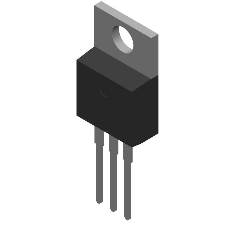
Available Download Formats
By downloading CAD models, you agree to our Terms & Conditions and Privacy Policy
CSD18532KCS Part Data Attributes
|
|
CSD18532KCS
Texas Instruments
Buy Now
Datasheet
|
Compare Parts:
CSD18532KCS
Texas Instruments
Power Field-Effect Transistor, 100A I(D), 60V, 0.0053ohm, 1-Element, N-Channel, Silicon, Metal-oxide Semiconductor FET, TO-220
|
| Pbfree Code | Yes | |
| Rohs Code | Yes | |
| Part Life Cycle Code | Active | |
| ECCN Code | EAR99 | |
| HTS Code | 8541.29.00.95 | |
| Additional Feature | Avalanche Rated, Logic Level Compatible | |
| Avalanche Energy Rating (Eas) | 281 Mj | |
| Case Connection | Drain | |
| Configuration | Single With Built-In Diode | |
| DS Breakdown Voltage-Min | 60 V | |
| Drain Current-Max (ID) | 100 A | |
| Drain-source On Resistance-Max | 0.0053 Ω | |
| FET Technology | Metal-Oxide Semiconductor | |
| Feedback Cap-Max (Crss) | 14 Pf | |
| JEDEC-95 Code | TO-220 | |
| JESD-30 Code | R-PSFM-T3 | |
| JESD-609 Code | e3 | |
| Number of Elements | 1 | |
| Number of Terminals | 3 | |
| Operating Mode | Enhancement Mode | |
| Operating Temperature-Max | 175 °C | |
| Operating Temperature-Min | -55 °C | |
| Package Body Material | Plastic/Epoxy | |
| Package Shape | Rectangular | |
| Package Style | Flange Mount | |
| Polarity/Channel Type | N-Channel | |
| Power Dissipation-Max (Abs) | 216 W | |
| Pulsed Drain Current-Max (IDM) | 400 A | |
| Surface Mount | No | |
| Terminal Finish | Matte Tin (Sn) - Annealed | |
| Terminal Form | Through-Hole | |
| Terminal Position | Single | |
| Transistor Application | Switching | |
| Transistor Element Material | Silicon |
Resources and Additional Insights for CSD18532KCS
Reference Designs related to CSD18532KCS
-
High Efficiency 410W AC/DC Power Supply Reference Design
PMP11282 is a high-efficiency AC/DC power supply reference design with universal AC input and 24V/17A output. Interleaved transition mode PFC and LLC series resonant converter is applied for 24V/17A main power. A PSR Flyback with MOSFET integrated controller is applied as the auxiliary supply. 91.98% efficiency is achieved at low line and full load. 94.61% efficiency is achieved at high line and full load.
-
98% Efficiency Analog 24V to 36V: 500W Backup and 50W Charger Reference Design for DC UPS
This analog: bidirectional power conversion reference design has a discharge or boost stage of 500 W and charge or buck stage of 50 W. This reference design is made for 24-V battery pack and 30-V to 38-V bus voltage for use in DC-UPS: battery backup unit (BBU): local energy storage (LES) and DC/DC brick modules. The design’s high efficiency of >98% discharge and >95% charge optimizes the thermal management and extends battery backup time.
-
High Efficiency 400W AC/DC Power Supply Reference Design
PMP11064 is a high-efficiency AC/DC power supply reference design with universal AC input and 20V/20A output. Interleaved transition mode PFC and LLC series resonant converter is applied for 20V/20A main power. A PSR Flyback with MOSFET integrated controller is applied as the auxiliary supply. 91.2% efficiency is achieved at low line and full load. 93.1% efficiency is achieved at high line and full load.
-
360W Phase Shift Full Bridge Resonant LLC with High Side Low Side Driver Reference Design
The power supply employs Full Bridge Resonant LLC with phase shift operating at ramp up: light load: low output voltage. This operating mode can replace PWM operating mode in LLC: which can improve efficiency signficantly in light load.
-
Novel: High Efficiency Full-Bridge Rectifier Reference Design
TIDA-00858 implements a high-efficiency approach to fullbridge rectifier. This reference design replaces diodes with four N-Channel MOSFETs:combined with LM74670-Q1 smart diode controllers in a full-bridge rectifier configuration. LM74670-Q1 is an effective zero-IQ replacement of diode loss. This design can produce a rectified DC voltage without diode forward voltage drop for AC-input voltage up to 45 V. It can handle AC input of 300-Hz frequency and up to 100-A output current with less thermal management compared to a schottky diode rectifier.
CSD18532KCS Frequently Asked Questions (FAQ)
-
The maximum operating temperature range for the CSD18532KCS is -40°C to 150°C.
-
To ensure stability, it's recommended to use a minimum output capacitance of 10uF, and a maximum ESR of 1 ohm. Additionally, the input capacitance should be at least 10uF with an ESR of 1 ohm or less.
-
The recommended input voltage range for the CSD18532KCS is 4.5V to 18V. Operating outside this range may affect the device's performance and reliability.
-
The output voltage of the CSD18532KCS can be calculated using the formula: Vout = (R1/R2) * (1 + R3/R4) * Vin, where R1, R2, R3, and R4 are the resistors in the feedback network.
-
The maximum current rating for the CSD18532KCS is 3A. Exceeding this current may cause the device to overheat or fail.