
| Part Number | Manufacturer | Composite Price | Description | Compare |
|---|---|---|---|---|
| SUM110N10-09-E3 | Vishay Intertechnologies | $2.7527 | Power Field-Effect Transistor, 110A I(D), 100V, 0.0095ohm, 1-Element, N-Channel, Silicon, Metal-oxide Semiconductor FET, TO-263AB | CSD19531KCS vs SUM110N10-09-E3 |
| APT10M09LVFR | Microsemi Corporation (now Microchip) | Check for Price | Power Field-Effect Transistor, 100A I(D), 100V, 0.009ohm, 1-Element, N-Channel, Silicon, Metal-oxide Semiconductor FET, TO-264AA | CSD19531KCS vs APT10M09LVFR |
| SUM110N10-09 | Vishay Siliconix | Check for Price | Power Field-Effect Transistor | CSD19531KCS vs SUM110N10-09 |
| SUM110N10-09 | Vishay Intertechnologies | Check for Price | Power Field-Effect Transistor, 110A I(D), 1-Element, N-Channel, Metal-oxide Semiconductor FET | CSD19531KCS vs SUM110N10-09 |
| IRFPS3810PBF | Infineon Technologies AG | Check for Price | Power Field-Effect Transistor, 105A I(D), 100V, 0.009ohm, 1-Element, N-Channel, Silicon, Metal-oxide Semiconductor FET | CSD19531KCS vs IRFPS3810PBF |
| IRFPS3810 | International Rectifier | Check for Price | Power Field-Effect Transistor, 105A I(D), 100V, 0.009ohm, 1-Element, N-Channel, Silicon, Metal-oxide Semiconductor FET | CSD19531KCS vs IRFPS3810 |
| APT10M09LVR | Advanced Power Technology | Check for Price | Power Field-Effect Transistor, 100A I(D), 100V, 0.009ohm, 1-Element, N-Channel, Silicon, Metal-oxide Semiconductor FET, TO-264AA | CSD19531KCS vs APT10M09LVR |
| IRFPS3810 | Infineon Technologies AG | Check for Price | Power Field-Effect Transistor, 105A I(D), 100V, 0.009ohm, 1-Element, N-Channel, Silicon, Metal-oxide Semiconductor FET | CSD19531KCS vs IRFPS3810 |
| BUK9610-100B,118 | Nexperia | Check for Price | Power Field-Effect Transistor, 75A I(D), 100V, 0.011ohm, 1-Element, N-Channel, Silicon, Metal-oxide Semiconductor FET | CSD19531KCS vs BUK9610-100B,118 |
| BUK9610-100B | Nexperia | Check for Price | Power Field-Effect Transistor, 110A I(D), 100V, 0.011ohm, 1-Element, N-Channel, Silicon, Metal-oxide Semiconductor FET | CSD19531KCS vs BUK9610-100B |
Part Details for CSD19531KCS by Texas Instruments
Results Overview of CSD19531KCS by Texas Instruments
- Distributor Offerings: (7 listings)
- Number of FFF Equivalents: (0 replacements)
- Tariff Estimator: (Available) NEW
- Number of Functional Equivalents: (10 options)
- CAD Models: (Available)
- Part Data Attributes: (Available)
- Reference Designs: (Available)
Tip: Data for a part may vary between manufacturers. You can filter for manufacturers on the top of the page next to the part image and part number.
CSD19531KCS Information
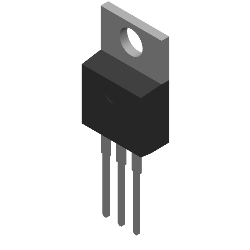
CSD19531KCS by Texas Instruments is a Power Field-Effect Transistor.
Power Field-Effect Transistors are under the broader part category of Transistors.
A transistor is a small semiconductor device used to amplify, control, or create electrical signals. When selecting a transistor, factors such as voltage, current rating, gain, and power dissipation must be considered, with common types. Read more about Transistors on our Transistors part category page.
Available Datasheets
| Part # | Manufacturer | Description | Datasheet |
|---|---|---|---|
| CSD19531KCS | Texas Instruments | 100V, N ch NexFET MOSFET™, single TO-220, 7.7mOhm 3-TO-220 -55 to 175 |
Price & Stock for CSD19531KCS
| Part # | Distributor | Description | Stock | Price | Buy | |
|---|---|---|---|---|---|---|
|
DISTI #
296-37480-5-ND
|
DigiKey | MOSFET N-CH 100V 100A TO220-3 Min Qty: 1 Container: Tube |
0 Tube |
|
$1.0157 / $2.8500 | Buy Now |
|
DISTI #
595-CSD19531KCS
|
Mouser Electronics | MOSFETs 100V 6.4mOhm Pwr MOS FET RoHS: Compliant | 0 |
|
$0.9020 / $2.8500 | Order Now |
|
|
Quest Components | 17 |
|
$2.1600 / $3.4560 | Buy Now | |
|
DISTI #
CSD19531KCS
|
TME | Transistor: N-MOSFET, unipolar, 100V, 100A, 214W, TO220-3 Min Qty: 1 | 61 |
|
$1.2100 / $2.5300 | Buy Now |
|
|
Chip Stock | 100-V, N channel NexFET™ power MOSFET, single TO-220, 7.7 mOhm 3-TO-220 -55 to 175 | 19500 |
|
RFQ | |
|
|
Vyrian | Power Field-Effect Transistor, 100A I(D), 100V, 0.0088ohm, 1-Element, N-Channel, Silicon, Metal-oxide Semiconductor FET, TO-220 | 9327 |
|
RFQ | |
|
|
Win Source Electronics | MOSFET N-CH 100V 100A TO220-3 | 2900 |
|
$1.1819 / $1.7728 | Buy Now |
US Tariff Estimator: CSD19531KCS by Texas Instruments
Calculations from this tool are estimations only for imports into the United States. Please refer to the distributor or manufacturer and reference official US government sources and authorities to verify any final purchase costs.
CSD19531KCS CAD Models
-
Part Symbol
-
Footprint
-
3D Model
Available Download Formats
By downloading CAD models, you agree to our Terms & Conditions and Privacy Policy
CSD19531KCS Part Data Attributes
|
|
CSD19531KCS
Texas Instruments
Buy Now
Datasheet
|
Compare Parts:
CSD19531KCS
Texas Instruments
Power Field-Effect Transistor, 100A I(D), 100V, 0.0088ohm, 1-Element, N-Channel, Silicon, Metal-oxide Semiconductor FET, TO-220
|
| Pbfree Code | Yes | |
| Rohs Code | Yes | |
| Part Life Cycle Code | Active | |
| ECCN Code | EAR99 | |
| HTS Code | 8541.29.00.95 | |
| Additional Feature | Avalanche Rated | |
| Avalanche Energy Rating (Eas) | 180 Mj | |
| Case Connection | Drain | |
| Configuration | Single With Built-In Diode | |
| DS Breakdown Voltage-Min | 100 V | |
| Drain Current-Max (ID) | 100 A | |
| Drain-source On Resistance-Max | 0.0088 Ω | |
| FET Technology | Metal-Oxide Semiconductor | |
| Feedback Cap-Max (Crss) | 17 Pf | |
| JEDEC-95 Code | TO-220 | |
| JESD-30 Code | R-PSFM-T3 | |
| JESD-609 Code | e3 | |
| Number of Elements | 1 | |
| Number of Terminals | 3 | |
| Operating Mode | Enhancement Mode | |
| Operating Temperature-Max | 175 °C | |
| Operating Temperature-Min | -55 °C | |
| Package Body Material | Plastic/Epoxy | |
| Package Shape | Rectangular | |
| Package Style | Flange Mount | |
| Polarity/Channel Type | N-Channel | |
| Power Dissipation-Max (Abs) | 179 W | |
| Pulsed Drain Current-Max (IDM) | 285 A | |
| Surface Mount | No | |
| Terminal Finish | Matte Tin (Sn) - Annealed | |
| Terminal Form | Through-Hole | |
| Terminal Position | Single | |
| Transistor Application | Switching | |
| Transistor Element Material | Silicon |
Alternate Parts for CSD19531KCS
This table gives cross-reference parts and alternative options found for CSD19531KCS. The Form Fit Function (FFF) tab will give you the options that are more likely to serve as direct pin-to-pin alternates or drop-in parts. The Functional Equivalents tab will give you options that are likely to match the same function of CSD19531KCS, but it may not fit your design. Always verify details of parts you are evaluating, as these parts are offered as suggestions for what you are looking for and are not guaranteed.
Resources and Additional Insights for CSD19531KCS
Reference Designs related to CSD19531KCS
- 400-W AC/DC reference design for avionics
-
60-W: Ultra-wide range power supply reference design
This reference design provides a 12-Vdc: 5-Vdc: and 3.3-Vdc output from an ultra-wide range of both AC and DC inputs. A universal 85 to 265-Vac input can be applied to the input of the quasi-resonant flyback. For DC inputs ranging from 24 to 150-Vdc: a boost creates a 150-V bus voltage that is fed to the QR flyback. If the input is 150 to 250-Vdc: the boost does not switch to improve efficiency while still powering the flyback and other down stream converters.
-
93% Efficiency: 400-W AC/DC reference design for avionics
This is a compact: 30-V DC: 400-W reference design for avionics applications: accepting main frequencies between 400 Hz and 800 Hz. This design consists of a front-end: two-phase interleaved transition mode (TM) power factor correction (PFC) based on UCC28064A. This minimizes the PFC inductor size and reduces EMI filter requirements. The DC/DC is implemented by employing HB-LLC stage: using UCC256404. For efficiency improvement: synchronous rectification is used at secondary side with FETs driven by UCC24612.
CSD19531KCS Frequently Asked Questions (FAQ)
-
A 2-layer or 4-layer PCB with a solid ground plane and thermal vias is recommended. Ensure a minimum of 1 oz copper thickness and a thermal relief pattern under the device.
-
Ensure the input voltage (VIN) is within the recommended range (4.5V to 18V). Use a high-quality decoupling capacitor (e.g., 10uF) close to the device. Verify the output voltage (VOUT) is within the specified range (0.8V to 3.3V).
-
A 10uF to 22uF ceramic capacitor (X5R or X7R dielectric) is recommended for input decoupling. Place the capacitor as close to the VIN pin as possible.
-
Ensure the input voltage (VIN) is applied before the enable signal (EN). The enable signal should be asserted after the input voltage has reached its nominal value.
-
The maximum allowed output current is 3A. However, the device can deliver up to 5A peak current for short durations (e.g., during startup or transient events).