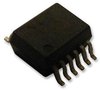

| Part Number | Manufacturer | Composite Price | Description | Compare |
|---|---|---|---|---|
| L5150CJTR | STMicroelectronics | $0.7859 | Fixed Positive LDO Regulator, 5V, 0.5V Dropout, BICMOS, PDSO12 | L5150CJ vs L5150CJTR |
Part Details for L5150CJ by STMicroelectronics
Results Overview of L5150CJ by STMicroelectronics
- Distributor Offerings: (2 listings)
- Number of FFF Equivalents: (1 replacement)
- Tariff Estimator: (Available) NEW
- Number of Functional Equivalents: (1 option)
- CAD Models: (Available)
- Part Data Attributes: (Available)
- Reference Designs: (Available)
Tip: Data for a part may vary between manufacturers. You can filter for manufacturers on the top of the page next to the part image and part number.
Applications
Consumer Electronics
Energy and Power Systems
Transportation and Logistics
Renewable Energy
Automotive
L5150CJ Information
L5150CJ by STMicroelectronics is a Linear Regulator IC.
Linear Regulator ICs are under the broader part category of Power Circuits.
A power circuit delivers electricity in order to operate a load for an electronic device. Power circuits include transformers, generators and switches. Read more about Power Circuits on our Power Circuits part category page.
Price & Stock for L5150CJ
| Part # | Distributor | Description | Stock | Price | Buy | |
|---|---|---|---|---|---|---|
|
DISTI #
511-L5150CJ
|
Mouser Electronics | LDO Voltage Regulators 5V MULTIFUNCTION LDO RoHS: Compliant | 0 |
|
Order Now | |
|
|
Vyrian | Fixed Positive LDO Regulator, 5V, 0.5V Dropout, BICMOS, PDSO12 | 5149 |
|
RFQ |
US Tariff Estimator: L5150CJ by STMicroelectronics
Calculations from this tool are estimations only for imports into the United States. Please refer to the distributor or manufacturer and reference official US government sources and authorities to verify any final purchase costs.
L5150CJ CAD Models
-
Part Symbol
-
Footprint
-
3D Model
Available Download Formats
By downloading CAD models, you agree to our Terms & Conditions and Privacy Policy
L5150CJ Part Data Attributes
|
|
L5150CJ
STMicroelectronics
Buy Now
Datasheet
|
Compare Parts:
L5150CJ
STMicroelectronics
Fixed Positive LDO Regulator, 5V, 0.5V Dropout, BICMOS, PDSO12
|
| Rohs Code | Yes | |
| Part Life Cycle Code | Active | |
| Part Package Code | SSOP | |
| Pin Count | 12 | |
| ECCN Code | EAR99 | |
| HTS Code | 8542.39.00.60 | |
| Adjustability | Fixed | |
| Dropout Voltage1-Max | 0.5 V | |
| Dropout Voltage1-Nom | 0.5 V | |
| Input Voltage Absolute-Max | 40 V | |
| Input Voltage-Max | 28 V | |
| Input Voltage-Min | 6 V | |
| JESD-30 Code | R-PDSO-G12 | |
| JESD-609 Code | e3 | |
| Length | 4.9 Mm | |
| Line Regulation-Max | 0.04% | |
| Load Regulation-Max | 0.055% | |
| Moisture Sensitivity Level | 3 | |
| Number of Functions | 1 | |
| Number of Outputs | 1 | |
| Number of Terminals | 12 | |
| Operating Temperature TJ-Max | 150 °C | |
| Operating Temperature TJ-Min | -40 °C | |
| Output Current1-Max | 0.15 A | |
| Output Voltage1-Max | 5.25 V | |
| Output Voltage1-Min | 4.75 V | |
| Output Voltage1-Nom | 5 V | |
| Package Body Material | Plastic/Epoxy | |
| Package Code | HLSSOP | |
| Package Equivalence Code | SOP12,.25,32 | |
| Package Shape | Rectangular | |
| Package Style | Small Outline | |
| Packing Method | Tube | |
| Peak Reflow Temperature (Cel) | 260 | |
| Qualification Status | Not Qualified | |
| Regulator Type | Fixed Positive Single Output Ldo Regulator | |
| Seated Height-Max | 1.62 Mm | |
| Surface Mount | Yes | |
| Technology | Bicmos | |
| Terminal Finish | Matte Tin (Sn) - Annealed | |
| Terminal Form | Gull Wing | |
| Terminal Pitch | 0.8 Mm | |
| Terminal Position | Dual | |
| Time@Peak Reflow Temperature-Max (s) | 30 | |
| Voltage Tolerance-Max | 5% | |
| Width | 3.9 Mm |
Alternate Parts for L5150CJ
This table gives cross-reference parts and alternative options found for L5150CJ. The Form Fit Function (FFF) tab will give you the options that are more likely to serve as direct pin-to-pin alternates or drop-in parts. The Functional Equivalents tab will give you options that are likely to match the same function of L5150CJ, but it may not fit your design. Always verify details of parts you are evaluating, as these parts are offered as suggestions for what you are looking for and are not guaranteed.
Resources and Additional Insights for L5150CJ
Reference Designs related to L5150CJ
-
Trunk Systems and LV Smart Locks
ST's comprehensive Automotive Discovery Ecosystem lets you quickly find the best solution for your automotive applications.<p>Our Automotive Trunk Control solution includes the SPC5-EV-ADIS adapter that you can combine with the SPC560B-DIS Discovery board along with VIPower "easy boards" addressing several motor drivers for automotive applications such as Trunk Lock, Power Lift gate, relay replacement, and more<p>ST, leading supplier of IC solutions for Smart Driving and IoT, provides a wide offer for the motor driving like:Smart DrivingPower trunk lifts<p>Power lift gates<p>Door locks<p>Cinch/ Latch systems<p>IoT and other applicationsRobotic vacuum cleaners<p>Window blinds<p>Smart door locks
L5150CJ Frequently Asked Questions (FAQ)
-
STMicroelectronics provides a recommended PCB layout in the application note AN4566, which includes guidelines for thermal vias, copper pours, and component placement to ensure optimal thermal performance.
-
The input capacitor selection depends on the input voltage, output voltage, and output current. A general guideline is to choose a capacitor with a voltage rating of at least 1.5 times the input voltage, and a capacitance value between 10uF to 100uF. Refer to the application note AN4566 for more detailed guidance.
-
The maximum allowed voltage drop across the internal switch is typically around 1.5V to 2V, depending on the operating conditions. Exceeding this voltage drop may lead to reduced efficiency, increased heat generation, or even damage to the device.
-
To ensure the L5150CJ operates within the SOA, monitor the input voltage, output current, and junction temperature. Avoid operating the device near the maximum ratings, and ensure proper thermal management and PCB design. Refer to the datasheet and application notes for more information.
-
The recommended output capacitor type is a low-ESR ceramic or film capacitor. The value depends on the output voltage and current, but a general guideline is to use a capacitor with a value between 10uF to 47uF. Refer to the application note AN4566 for more detailed guidance.