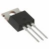
Part Details for STF9NK80Z by STMicroelectronics
Results Overview of STF9NK80Z by STMicroelectronics
- Distributor Offerings: (1 listing)
- Number of FFF Equivalents: (0 replacements)
- Tariff Estimator: (Not Available)
- Number of Functional Equivalents: (0 options)
- CAD Models: (Request Part)
- Part Data Attributes: (Available)
- Reference Designs: (Not Available)
Tip: Data for a part may vary between manufacturers. You can filter for manufacturers on the top of the page next to the part image and part number.
STF9NK80Z Information
STF9NK80Z by STMicroelectronics is a Power Field-Effect Transistor.
Power Field-Effect Transistors are under the broader part category of Transistors.
A transistor is a small semiconductor device used to amplify, control, or create electrical signals. When selecting a transistor, factors such as voltage, current rating, gain, and power dissipation must be considered, with common types. Read more about Transistors on our Transistors part category page.
Price & Stock for STF9NK80Z
| Part # | Distributor | Description | Stock | Price | Buy | |
|---|---|---|---|---|---|---|
|
|
Vyrian | Power Field-Effect Transistor, 7.5A I(D), 800V, 1.2ohm, 1-Element, N-Channel, Silicon, Metal-oxide Semiconductor FET, TO-220AB | 8470 |
|
RFQ |
STF9NK80Z Part Data Attributes
|
|
STF9NK80Z
STMicroelectronics
Buy Now
Datasheet
|
Compare Parts:
STF9NK80Z
STMicroelectronics
Power Field-Effect Transistor, 7.5A I(D), 800V, 1.2ohm, 1-Element, N-Channel, Silicon, Metal-oxide Semiconductor FET, TO-220AB
|
| Rohs Code | Yes | |
| Part Life Cycle Code | Obsolete | |
| Part Package Code | TO-220AB | |
| Package Description | To-220fp, 3 Pin | |
| Pin Count | 3 | |
| Similar Group | Tr0810021002yyyy10059142 | |
| ECCN Code | EAR99 | |
| Additional Feature | Avalanche Rated | |
| Avalanche Energy Rating (Eas) | 350 Mj | |
| Case Connection | Isolated | |
| Configuration | Single With Built-In Diode | |
| DS Breakdown Voltage-Min | 800 V | |
| Drain Current-Max (ID) | 7.5 A | |
| Drain-source On Resistance-Max | 1.2 Ω | |
| FET Technology | Metal-Oxide Semiconductor | |
| Feedback Cap-Max (Crss) | 10 Pf | |
| JEDEC-95 Code | TO-220AB | |
| JESD-30 Code | R-PSFM-T3 | |
| JESD-609 Code | e3 | |
| Number of Elements | 1 | |
| Number of Terminals | 3 | |
| Operating Mode | Enhancement Mode | |
| Operating Temperature-Max | 150 °C | |
| Package Body Material | Plastic/Epoxy | |
| Package Shape | Rectangular | |
| Package Style | Flange Mount | |
| Polarity/Channel Type | N-Channel | |
| Power Dissipation-Max (Abs) | 35 W | |
| Pulsed Drain Current-Max (IDM) | 30 A | |
| Qualification Status | Not Qualified | |
| Surface Mount | No | |
| Terminal Finish | Tin (Sn) | |
| Terminal Form | Through-Hole | |
| Terminal Position | Single | |
| Transistor Application | Switching | |
| Transistor Element Material | Silicon |
STF9NK80Z Frequently Asked Questions (FAQ)
-
The maximum operating temperature range for the STF9NK80Z is -40°C to 150°C, as specified in the datasheet. However, it's recommended to operate within -20°C to 125°C for optimal performance and reliability.
-
To ensure proper biasing, follow the recommended voltage and current ratings in the datasheet. Typically, a voltage supply of 12V to 15V is recommended, with a current limit of 1A to 2A. Additionally, ensure the device is properly decoupled with capacitors to minimize noise and oscillations.
-
For optimal thermal management, use a multi-layer PCB with a solid ground plane and thermal vias to dissipate heat. Keep the device away from heat sources and ensure good airflow. Use a thermal pad or heat sink to further improve heat dissipation. Follow STMicroelectronics' recommended PCB layout guidelines for the STF9NK80Z.
-
Use overvoltage protection (OVP) and overcurrent protection (OCP) circuits to prevent damage to the device. OVP can be achieved using a voltage regulator or a zener diode, while OCP can be implemented using a current sense resistor and a comparator. Additionally, consider using a fuse or a polyfuse to protect against overcurrent conditions.
-
The recommended gate drive circuits for the STF9NK80Z include a bootstrap circuit or a dedicated gate driver IC. The bootstrap circuit uses a diode and a capacitor to generate the gate drive voltage, while a dedicated gate driver IC provides a more robust and efficient solution. Consult the datasheet and application notes for specific circuit recommendations.