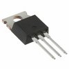
Part Details for STTH16R04CFP by STMicroelectronics
Results Overview of STTH16R04CFP by STMicroelectronics
- Distributor Offerings: (1 listing)
- Number of FFF Equivalents: (0 replacements)
- Tariff Estimator: (Available) NEW
- Number of Functional Equivalents: (0 options)
- CAD Models: (Request Part)
- Part Data Attributes: (Available)
- Reference Designs: (Not Available)
Tip: Data for a part may vary between manufacturers. You can filter for manufacturers on the top of the page next to the part image and part number.
STTH16R04CFP Information
STTH16R04CFP by STMicroelectronics is a Rectifier Diode.
Rectifier Diodes are under the broader part category of Diodes.
A diode is a electrical part that can control the direction in which the current flows in a device. Consider factors like voltage drop, current capacity, reverse voltage, and operating frequency when selecting a diode. Read more about Diodes on our Diodes part category page.
Price & Stock for STTH16R04CFP
| Part # | Distributor | Description | Stock | Price | Buy | |
|---|---|---|---|---|---|---|
|
|
Vyrian | Rectifier Diode, 1 Phase, 2 Element, 8A, 400V V(RRM), Silicon, TO-220AB | 6017 |
|
RFQ |
US Tariff Estimator: STTH16R04CFP by STMicroelectronics
Calculations from this tool are estimations only for imports into the United States. Please refer to the distributor or manufacturer and reference official US government sources and authorities to verify any final purchase costs.
STTH16R04CFP Part Data Attributes
|
|
STTH16R04CFP
STMicroelectronics
Buy Now
Datasheet
|
Compare Parts:
STTH16R04CFP
STMicroelectronics
Rectifier Diode, 1 Phase, 2 Element, 8A, 400V V(RRM), Silicon, TO-220AB
|
| Rohs Code | Yes | |
| Part Life Cycle Code | Obsolete | |
| Part Package Code | TO-220AB | |
| Package Description | To-220fpab, 3 Pin | |
| Pin Count | 3 | |
| ECCN Code | EAR99 | |
| HTS Code | 8541.10.00.80 | |
| Additional Feature | Free Wheeling Diode | |
| Application | Ultra Fast Recovery | |
| Case Connection | Isolated | |
| Configuration | Common Cathode, 2 Elements | |
| Diode Element Material | Silicon | |
| Diode Type | Rectifier Diode | |
| Forward Voltage-Max (VF) | 1.75 V | |
| JEDEC-95 Code | TO-220AB | |
| JESD-30 Code | R-PSFM-T3 | |
| Non-rep Pk Forward Current-Max | 120 A | |
| Number of Elements | 2 | |
| Number of Phases | 1 | |
| Number of Terminals | 3 | |
| Operating Temperature-Max | 175 °C | |
| Operating Temperature-Min | -40 °C | |
| Output Current-Max | 8 A | |
| Package Body Material | Plastic/Epoxy | |
| Package Shape | Rectangular | |
| Package Style | Flange Mount | |
| Peak Reflow Temperature (Cel) | Not Specified | |
| Qualification Status | Not Qualified | |
| Rep Pk Reverse Voltage-Max | 400 V | |
| Reverse Current-Max | 10 µA | |
| Reverse Recovery Time-Max | 0.05 µS | |
| Reverse Test Voltage | 400 V | |
| Surface Mount | No | |
| Terminal Form | Through-Hole | |
| Terminal Position | Single | |
| Time@Peak Reflow Temperature-Max (s) | Not Specified |
STTH16R04CFP Frequently Asked Questions (FAQ)
-
STMicroelectronics provides a recommended PCB layout in their application note AN5042, which includes guidelines for thermal vias, copper pours, and component placement to minimize thermal resistance and ensure optimal performance.
-
To ensure reliable operation at high temperatures, it's essential to follow the recommended operating conditions, including junction temperature (Tj) and ambient temperature (Ta). Additionally, consider using thermal interface materials, such as thermal pads or thermal grease, to improve heat transfer between the device and the heat sink.
-
While the datasheet specifies the recommended operating voltage range, it's essential to note that the absolute maximum rating for the input pins is typically 20% above the recommended maximum voltage. However, it's always best to consult with STMicroelectronics' support team or a qualified engineer to determine the specific voltage limits for your application.
-
To troubleshoot issues with the device not turning on or not functioning correctly, start by verifying the power supply voltage, checking for proper pin connections, and ensuring that the device is properly soldered. If the issue persists, consult the datasheet and application notes for troubleshooting guidelines or contact STMicroelectronics' support team for assistance.
-
To prevent electrostatic discharge (ESD) damage, follow standard ESD protection measures, such as using anti-static wrist straps, mats, and bags, and handling the devices in a controlled environment with minimal humidity. Additionally, ensure that the devices are stored in their original packaging or in a protective container to prevent damage during transportation and storage.