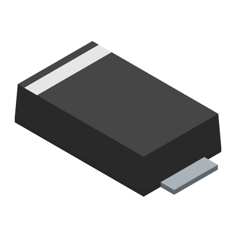
| Part Number | Manufacturer | Composite Price | Description | Compare |
|---|---|---|---|---|
| STPS3170AF | STMicroelectronics | $0.2684 | Rectifier Diode, Schottky, 1 Phase, 1 Element, 3A, 170V V(RRM), Silicon | STPS3170AFN vs STPS3170AF |
Part Details for STPS3170AFN by STMicroelectronics
Results Overview of STPS3170AFN by STMicroelectronics
- Distributor Offerings: (0 listings)
- Number of FFF Equivalents: (0 replacements)
- Tariff Estimator: (Available) NEW
- Number of Functional Equivalents: (1 option)
- CAD Models: (Available)
- Part Data Attributes: (Available)
- Reference Designs: (Not Available)
Tip: Data for a part may vary between manufacturers. You can filter for manufacturers on the top of the page next to the part image and part number.
Applications
Consumer Electronics
Space Technology
Aerospace and Defense
Energy and Power Systems
Transportation and Logistics
Renewable Energy
Automotive
STPS3170AFN Information
STPS3170AFN by STMicroelectronics is a Rectifier Diode.
Rectifier Diodes are under the broader part category of Diodes.
A diode is a electrical part that can control the direction in which the current flows in a device. Consider factors like voltage drop, current capacity, reverse voltage, and operating frequency when selecting a diode. Read more about Diodes on our Diodes part category page.
US Tariff Estimator: STPS3170AFN by STMicroelectronics
Calculations from this tool are estimations only for imports into the United States. Please refer to the distributor or manufacturer and reference official US government sources and authorities to verify any final purchase costs.
STPS3170AFN CAD Models
-
Part Symbol
-
Footprint
-
3D Model
Available Download Formats
By downloading CAD models, you agree to our Terms & Conditions and Privacy Policy
STPS3170AFN Part Data Attributes
|
|
STPS3170AFN
STMicroelectronics
Buy Now
Datasheet
|
Compare Parts:
STPS3170AFN
STMicroelectronics
Rectifier Diode, Schottky, 1 Phase, 1 Element, 3A, 170V V(RRM), Silicon
|
| Rohs Code | Yes | |
| Part Life Cycle Code | Obsolete | |
| Package Description | Sma, 2 Pin | |
| ECCN Code | EAR99 | |
| HTS Code | 8541.10.00.80 | |
| Additional Feature | Free Wheeling Diode, Low Leakage Current | |
| Application | Efficiency | |
| Configuration | Single | |
| Diode Element Material | Silicon | |
| Diode Type | Rectifier Diode | |
| Forward Voltage-Max (VF) | 0.89 V | |
| JESD-30 Code | R-PDSO-F2 | |
| Non-rep Pk Forward Current-Max | 75 A | |
| Number of Elements | 1 | |
| Number of Phases | 1 | |
| Number of Terminals | 2 | |
| Operating Temperature-Max | 175 °C | |
| Output Current-Max | 3 A | |
| Package Body Material | Plastic/Epoxy | |
| Package Shape | Rectangular | |
| Package Style | Small Outline | |
| Packing Method | Tr | |
| Rep Pk Reverse Voltage-Max | 170 V | |
| Reverse Current-Max | 4 µA | |
| Reverse Test Voltage | 170 V | |
| Surface Mount | Yes | |
| Technology | Schottky | |
| Terminal Form | Flat | |
| Terminal Position | Dual |
Alternate Parts for STPS3170AFN
This table gives cross-reference parts and alternative options found for STPS3170AFN. The Form Fit Function (FFF) tab will give you the options that are more likely to serve as direct pin-to-pin alternates or drop-in parts. The Functional Equivalents tab will give you options that are likely to match the same function of STPS3170AFN, but it may not fit your design. Always verify details of parts you are evaluating, as these parts are offered as suggestions for what you are looking for and are not guaranteed.
STPS3170AFN Frequently Asked Questions (FAQ)
-
A good PCB layout for optimal thermal performance involves placing the device near a thermal pad or a heat sink, and ensuring good thermal conductivity between the device and the PCB. A 2-layer or 4-layer PCB with a solid ground plane is recommended. Avoid placing thermal vias under the device, and ensure that the PCB is designed to minimize thermal resistance.
-
To ensure reliable operation in high-temperature environments, ensure that the device is operated within its recommended operating temperature range (-40°C to 150°C). Implement proper thermal management, such as heat sinks or thermal interfaces, to keep the device temperature below 125°C. Also, ensure that the PCB is designed to withstand high temperatures and that the device is properly soldered.
-
The recommended soldering conditions for the STPS3170AFN are: peak temperature of 260°C, soldering time of 10-30 seconds, and a temperature slope of 3°C/s. Ensure that the PCB is designed to withstand these soldering conditions, and that the device is properly cleaned and dried before soldering.
-
To protect the device from electrostatic discharge (ESD), ensure that all personnel handling the device wear anti-static wrist straps or use anti-static mats. Use ESD-protected packaging and storage materials, and ensure that the device is properly grounded during handling and assembly. Implement ESD protection circuits in the system design, such as TVS diodes or ESD protection arrays.
-
The recommended input and output capacitors for the STPS3170AFN are X7R or X5R ceramic capacitors with a voltage rating of 10V or higher. The input capacitor should be 1-10uF, and the output capacitor should be 1-22uF. Ensure that the capacitors are placed close to the device and have low equivalent series resistance (ESR) and inductance (ESL).