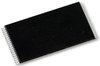
Part Details for M29F080D70N1 by STMicroelectronics
Results Overview of M29F080D70N1 by STMicroelectronics
- Distributor Offerings: (1 listing)
- Number of FFF Equivalents: (10 replacements)
- Tariff Estimator: (Available) NEW
- Number of Functional Equivalents: (10 options)
- CAD Models: (Request Part)
- Part Data Attributes: (Available)
- Reference Designs: (Not Available)
Tip: Data for a part may vary between manufacturers. You can filter for manufacturers on the top of the page next to the part image and part number.
M29F080D70N1 Information
M29F080D70N1 by STMicroelectronics is a Flash Memory.
Flash Memories are under the broader part category of Memory Components.
Memory components are essential in electronics for computer processing. They can be volatile or non-volatile, depending on the desired function. Read more about Memory Components on our Memory part category page.
Price & Stock for M29F080D70N1
| Part # | Distributor | Description | Stock | Price | Buy | |
|---|---|---|---|---|---|---|
|
DISTI #
M29F080D70N1-ND
|
DigiKey | IC FLASH 8MBIT PARALLEL 40TSOP Min Qty: 720 Container: Tray |
0 Tray |
|
$4.5032 | Buy Now |
US Tariff Estimator: M29F080D70N1 by STMicroelectronics
Calculations from this tool are estimations only for imports into the United States. Please refer to the distributor or manufacturer and reference official US government sources and authorities to verify any final purchase costs.
M29F080D70N1 Part Data Attributes
|
|
M29F080D70N1
STMicroelectronics
Buy Now
Datasheet
|
Compare Parts:
M29F080D70N1
STMicroelectronics
Flash, 1MX8, 70ns, PDSO40
|
| Rohs Code | Yes | |
| Part Life Cycle Code | Transferred | |
| Part Package Code | TSOP | |
| Package Description | 10 X 20 Mm, Plastic, Tsop-40 | |
| Pin Count | 40 | |
| ECCN Code | EAR99 | |
| HTS Code | 8542.32.00.51 | |
| Access Time-Max | 70 Ns | |
| JESD-30 Code | R-PDSO-G40 | |
| JESD-609 Code | e0 | |
| Length | 18.4 Mm | |
| Memory Density | 8388608 Bit | |
| Memory IC Type | Flash | |
| Memory Width | 8 | |
| Number of Functions | 1 | |
| Number of Terminals | 40 | |
| Number of Words | 1048576 Words | |
| Number of Words Code | 1000000 | |
| Operating Mode | Asynchronous | |
| Operating Temperature-Max | 70 °C | |
| Operating Temperature-Min | ||
| Organization | 1mx8 | |
| Package Body Material | Plastic/Epoxy | |
| Package Code | TSOP1 | |
| Package Shape | Rectangular | |
| Package Style | Small Outline, Thin Profile | |
| Parallel/Serial | Parallel | |
| Programming Voltage | 5 V | |
| Qualification Status | Not Qualified | |
| Seated Height-Max | 1.2 Mm | |
| Supply Voltage-Max (Vsup) | 5.5 V | |
| Supply Voltage-Min (Vsup) | 4.5 V | |
| Supply Voltage-Nom (Vsup) | 5 V | |
| Surface Mount | Yes | |
| Technology | Cmos | |
| Temperature Grade | Commercial | |
| Terminal Finish | Tin Lead | |
| Terminal Form | Gull Wing | |
| Terminal Pitch | 0.5 Mm | |
| Terminal Position | Dual | |
| Type | Nor Type | |
| Width | 10 Mm |
Alternate Parts for M29F080D70N1
This table gives cross-reference parts and alternative options found for M29F080D70N1. The Form Fit Function (FFF) tab will give you the options that are more likely to serve as direct pin-to-pin alternates or drop-in parts. The Functional Equivalents tab will give you options that are likely to match the same function of M29F080D70N1, but it may not fit your design. Always verify details of parts you are evaluating, as these parts are offered as suggestions for what you are looking for and are not guaranteed.
M29F080D70N1 Frequently Asked Questions (FAQ)
-
The M29F080D70N1 has a minimum of 100,000 erase cycles per sector, and a total of 1,000,000 erase cycles per device.
-
The HOLD# signal should be kept low during read and write operations to ensure that the device is not put into a hold state. If the HOLD# signal is asserted high, the device will enter a hold state and all operations will be suspended.
-
The recommended power-up sequence is to apply VCC first, followed by VPP (if used), and then the clock signal. This ensures that the device is properly initialized and ready for operation.
-
The device density and organization can be determined by reading the device ID and sector protection registers. The device ID register contains information about the device density, and the sector protection registers indicate the organization of the device.
-
The Write Enable Latch (WEL) bit is used to enable or disable write operations to the device. When WEL is set to 1, write operations are enabled, and when WEL is set to 0, write operations are disabled.